
Underground coal gasification deep hole ignition system and method

An underground gasification and ignition system technology, applied in coal gasification, underground mining, construction, etc., can solve the problems of burnout, igniter contact, and inability to ignite coal seams, and achieve the effect of avoiding impact

Active Publication Date: 2017-12-12
天津市地质研究和海洋地质中心 +1
View PDF6 Cites 5 Cited by
  • Summary
  • Abstract
  • Description
  • Claims
  • Application Information

AI Technical Summary

Problems solved by technology

The disadvantages of this method are: (1) when the borehole is deep, the coke may burn out and extinguish during the falling process; (2) when there is water at the bottom of the borehole, the hot coke will be extinguished when it encounters water; It may block the drilling, affect the next ignition work, increase the resistance of the gasification process, and then increase the operating cost. Therefore, coke ignition sometimes cannot ignite the coal seam, and the risk is greater
Electric ignition has the advantages of simplicity and safety, but sometimes the igniter cannot be in good contact with the coal seam, and the ignition time is longer in the presence of groundwater

Method used


Image

  • Underground coal gasification deep hole ignition system and method
  • Underground coal gasification deep hole ignition system and method
  • Underground coal gasification deep hole ignition system and method

Examples


Embodiment Construction

[0042] The structure of the ignition system of the present invention will be described in detail below in conjunction with the accompanying drawings.

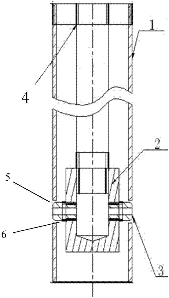
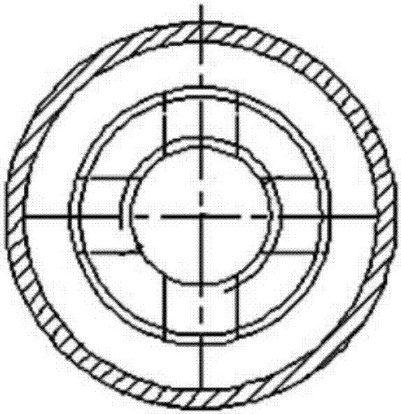
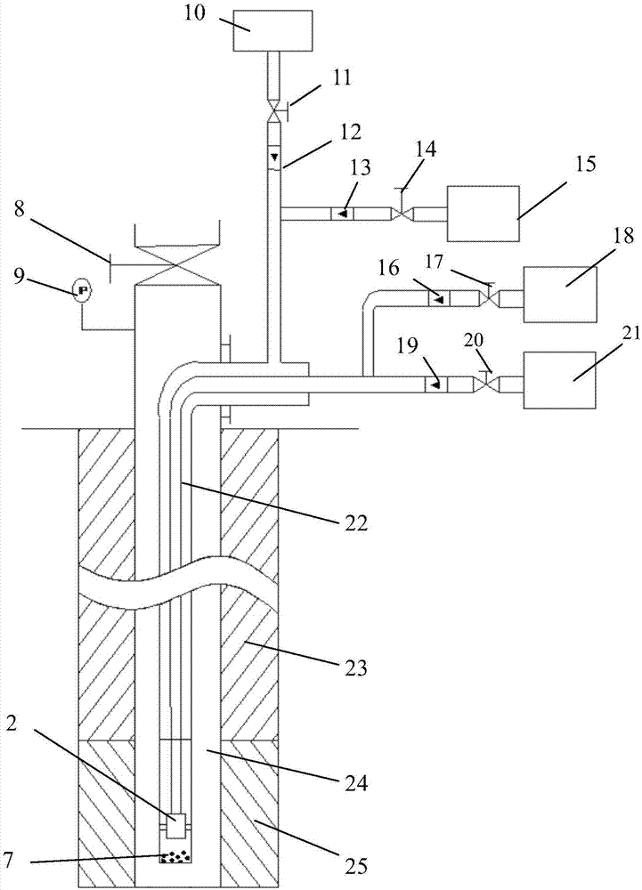
[0043] Such as Figure 1-Figure 3As shown, the ignition system of the present invention includes a double-sleeved gas delivery pipe 22, an ignition device, an oxygen supply device, an air supply device, a self-igniting agent delivery device and a combustion aid delivery device. One end of the double-sleeve gas delivery pipe 22 extends into the ignition borehole 24 and is connected with the ignition device. One end of the double-sleeve air delivery pipe 22 stretches out of the ignition borehole 24, and the outer pipe of this end is selectively communicated with the oxygen supply device and / or the air supply device (that is: it can only be connected with the oxygen supply device or the air supply device It can also be communicated with the oxygen supply device and the air supply device at the same time, and the opening of the pi...


PUM

PropertyMeasurementUnit
Lengthaaaaaaaaaa

Abstract

The invention discloses an underground coal gasification deep hole ignition system and method. The system is characterized in that one end of a double-sleeve gas conveying pipe extends out of an ignition hole, the outer pipe of the end is connected with an oxygen supply device and / or an air supply device, and the inner pipe of the end is connected with a spontaneous-combustion-agent conveying device and a combustion-supporting-agent conveying device; an ignition device comprises an outer sleeve, an inner sleeve, a nozzle seat and at least three ignition nozzles, the outer sleeve and the inner sleeve are respectively connected with the outer pipe and the inner pipe of the double-sleeve gas conveying pipe, and the lower portion of the inner sleeve is fixedly connected with the nozzle seat; the circumferential direction of the inner sleeve is provided with threaded through holes which are arranged in an equal-distance manner and are adaptive to the ignition nozzles in number and position, and one end of each ignition nozzle is mounted at the corresponding threaded through hole; a corresponding hole is formed in a position, corresponding to the position of the other end of each ignition nozzle, of the outer sleeve, and a gap is formed between each hole and the end face of the corresponding ignition nozzle; the bottom of the outer sleeve is sealed, and metallic sodium wrapped by paraffin is placed at the bottom of the outer sleeve; the top of the ignition hole is selectively sealed by a pipeline, and the pipeline is provided with a pressure gauge and a valve.

Description

technical field [0001] The invention relates to the technical field of underground coal gasification technology, in particular to an underground coal gasification deep hole ignition system and an ignition method. Background technique [0002] Underground coal gasification is the process of controlled combustion of underground coal to generate combustible gas through pyrolysis and chemical action of coal. To realize underground coal gasification, the coal in the underground coal seam must first be ignited. There are two main types of underground coal gasification technology: mine-type underground gasification and drilling-type underground gasification. [0003] Mine-type underground gasification is to manually develop tunnels and arrange underground gasifiers in the coal seam, so that people can go down into the coal seam and make sufficient preparations for gasification in the coal seam. The drilling type gasification is drilled into the coal seam, and then ignites the coal...

Claims


Application Information

Patent Timeline
IPC IPC(8): E21B43/295
CPCE21B43/295Y02E10/10
Inventor 王志刚石文学梁杰曹健江胜国付小锦付方建肖飞王喆李玉龙郭维韩芳鲁庆伟杨秀俊贾超詹健田麒徐峰王西玉李宏臣王雨
Owner 天津市地质研究和海洋地质中心
Learn More