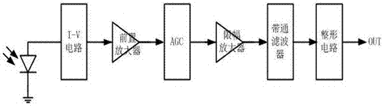
I-V circuit of infrared receiving module
An infrared receiving and circuit technology, applied in non-electrical signal transmission systems, signal transmission systems, instruments, etc., can solve problems such as poor circuit performance, and achieve the effect of improving PSRR and performance
- Summary
- Abstract
- Description
- Claims
- Application Information
AI Technical Summary
Problems solved by technology
Method used
Image

Examples
Embodiment Construction
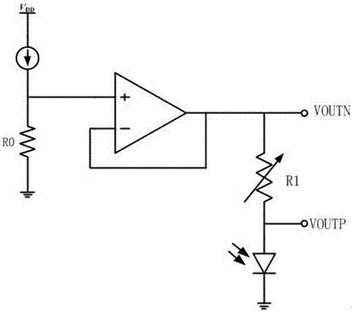
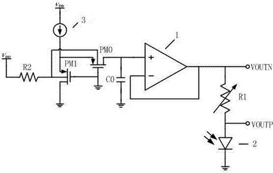
[0012] See image 3 As shown, an I-V circuit of an infrared receiving module includes an operational amplifier 1, a PMOS transistor PM0 and a PMOS transistor PM1. Resistor R1 and photodiode 2, the photodiode here is externally connected, that is figure 1 In the leftmost photodiode, the two ends of the adjustable resistor R1 are the voltage signal output terminals VOUTN and VOUTP respectively, and the output voltage signal is sent to the preamplifier at the rear end. The source terminals of the PMOS transistor PM0 and PMOS transistor PM1 are connected to the current source One end of 3 and the bulk end are connected, and one end of the resistor R2 is connected, and the gate end is connected to the ground, the other end of the current source 3 and the other end of the resistor are both connected to the power supply VDD, the drain end of the PMOS transistor PM1 is grounded, and the drain end of the PMOS transistor PM0 is connected to the operational amplifier. The non-inverting ...
PUM
 Abstract
Description
Claims
Application Information
 - R&D
- Intellectual Property
- Life Sciences
- Materials
- Tech Scout
- Unparalleled Data Quality
- Higher Quality Content
- 60% Fewer Hallucinations
Browse by: Latest US Patents, China's latest patents, Technical Efficacy Thesaurus, Application Domain, Technology Topic, Popular Technical Reports.
© 2025 PatSnap. All rights reserved.Legal|Privacy policy|Modern Slavery Act Transparency Statement|Sitemap|About US| Contact US: help@patsnap.com