
Rotor for electric machine

A rotor and rotor body technology, applied in the direction of electromechanical devices, electrical components, electric components, etc.

Active Publication Date: 2017-12-05
VOLKSWAGEN AG
View PDF5 Cites 11 Cited by
  • Summary
  • Abstract
  • Description
  • Claims
  • Application Information

AI Technical Summary

Problems solved by technology

This results in a cooling of the rotor body arranged on the rotor shaft, which however is not sufficient to ensure trouble-free operation of the electric machine, especially in electric machines for the vehicle drive

Method used


Image

  • Rotor for electric machine
  • Rotor for electric machine
  • Rotor for electric machine

Examples


Embodiment Construction

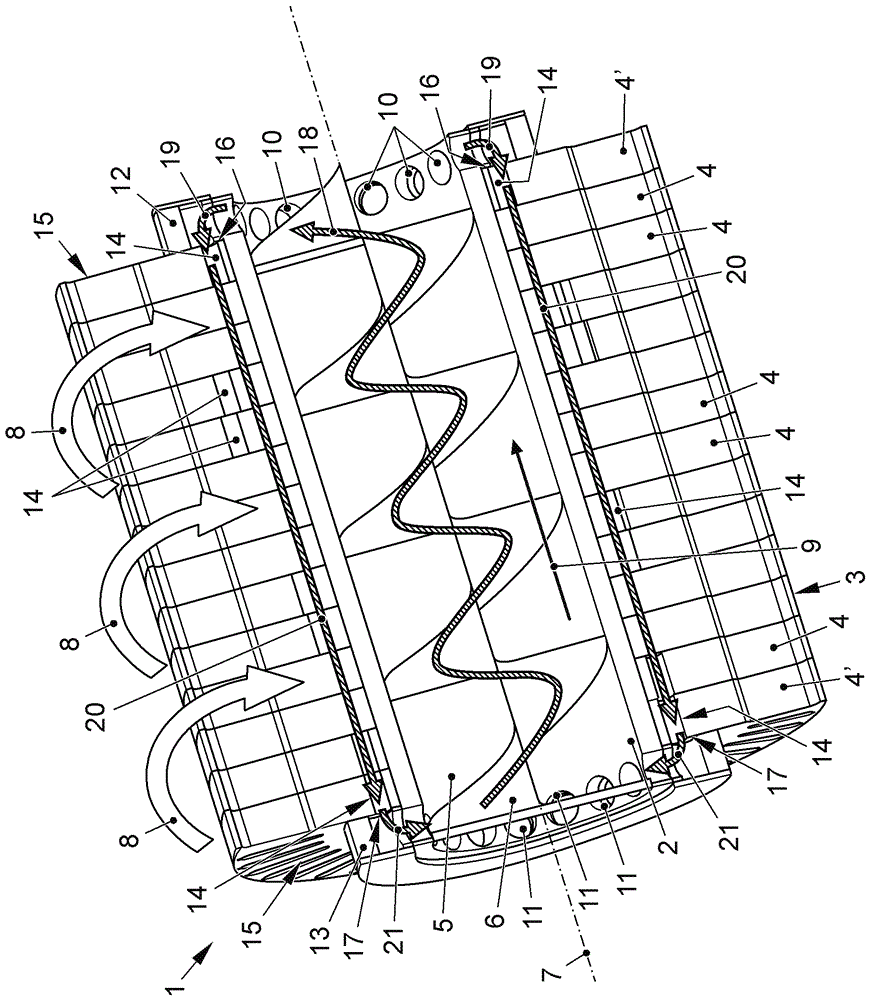
[0057] figure 1 and 2Different views of a rotor 1 for an electrical machine (not shown) with internal rotor cooling according to the invention are shown. The rotor 1 consists of a rotor shaft designed as a hollow shaft 2 and a rotor body 3 arranged on the rotor shaft in a rotationally fixed manner or connected thereto. The rotor body 3 is designed as a rotor lamination pack consisting of a plurality of rotor laminations 4 , 4 ′. In the inner space 5 of the hollow shaft 2 , the delivery spindle 6 is arranged in a rotationally fixed manner, in particular so as to be retracted into the hollow shaft 2 . During operation of the electric machine, the rotor body 3 , the hollow shaft 2 and the delivery spindle 6 jointly rotate about the axis of rotation 7 . This rotation is indicated by one or more directional arrows 8 .

[0058] In order to absorb the waste heat of the rotor 1 generated during the operation of the electric machine, a cooling fluid is provided which is guided or c...


PUM


Abstract

A rotor for an electric machine is formed of a rotor shaft and a rotor body which is non-rotatably mounted on the rotor shaft. At least sections of the rotor shaft are configured as a hollow shaft. A delivery screw is non-rotatably mounted in the hollow shaft for conveying a cooling fluid in a first direction through the hollow shaft. In order to provide an improved cooling of the rotor, the rotor body is formed with at least one cooling channel which extends in the axial direction. The cooling channel has an end-face inlet opening and an end-face outlet opening positioned on the opposite side for the cooling fluid. The cooling fluid conveyed in the first direction through the hollow shaft can be at least partially directed through the inlet opening into the cooling channel and conveyed in a second direction, which is counter to the first direction, to the outlet opening.

Description

technical field [0001] The invention relates to a rotor for an electric machine, comprising a rotor shaft and a rotor body arranged in a rotationally fixed manner on the rotor shaft, wherein the rotor shaft is designed at least in sections as a hollow shaft, and the delivery spindle is arranged in a hollow shaft in a rotationally fixed manner. In the shaft, cooling fluid can be guided in a first direction through the hollow shaft by means of the delivery spindle. Background technique [0002] The electric machine can be used on the one hand as a generator for generating electric current and on the other hand as a drive motor, in particular also as a drive for a motor vehicle. The electric machine has a stator and a rotatably mounted rotor. Losses occurring during operation of the electric machine, such as current heat losses and remagnetization and eddy current losses, lead to heating of the components of the electric machine. For reliable operation of the electric machine...

Claims


Application Information

Patent Timeline
Patent Type & Authority Applications(China)
IPC IPC(8): H02K1/32
CPCH02K1/32H02K9/197
Inventor S.格吕茨纳C.里姆
Owner VOLKSWAGEN AG
Learn More