
Bearing device with separate axial and radial supports for intermediate shafts in disconnect clutches for hybrid modules

A technology for separating clutches and intermediate shafts, which is applied to clutches, friction clutches, electric clutches, etc., can solve the problems of limited axial structure space design and large axial structure space, and achieves optimization of radial structure space and reduction of structure. The effect of space and structural space optimization

Active Publication Date: 2019-07-26
SCHAEFFLER TECH AG & CO KG
View PDF6 Cites 0 Cited by
  • Summary
  • Abstract
  • Description
  • Claims
  • Application Information

AI Technical Summary

Problems solved by technology

[0006] However, the disadvantage of these arrangements is that they take up a large axial construction space
Axial installation space can be designed very limited especially in the case of engines with a torque of less than 300 Nm based on customer requirements

Method used


Image

  • Bearing device with separate axial and radial supports for intermediate shafts in disconnect clutches for hybrid modules
  • Bearing device with separate axial and radial supports for intermediate shafts in disconnect clutches for hybrid modules
  • Bearing device with separate axial and radial supports for intermediate shafts in disconnect clutches for hybrid modules

Examples


Embodiment Construction

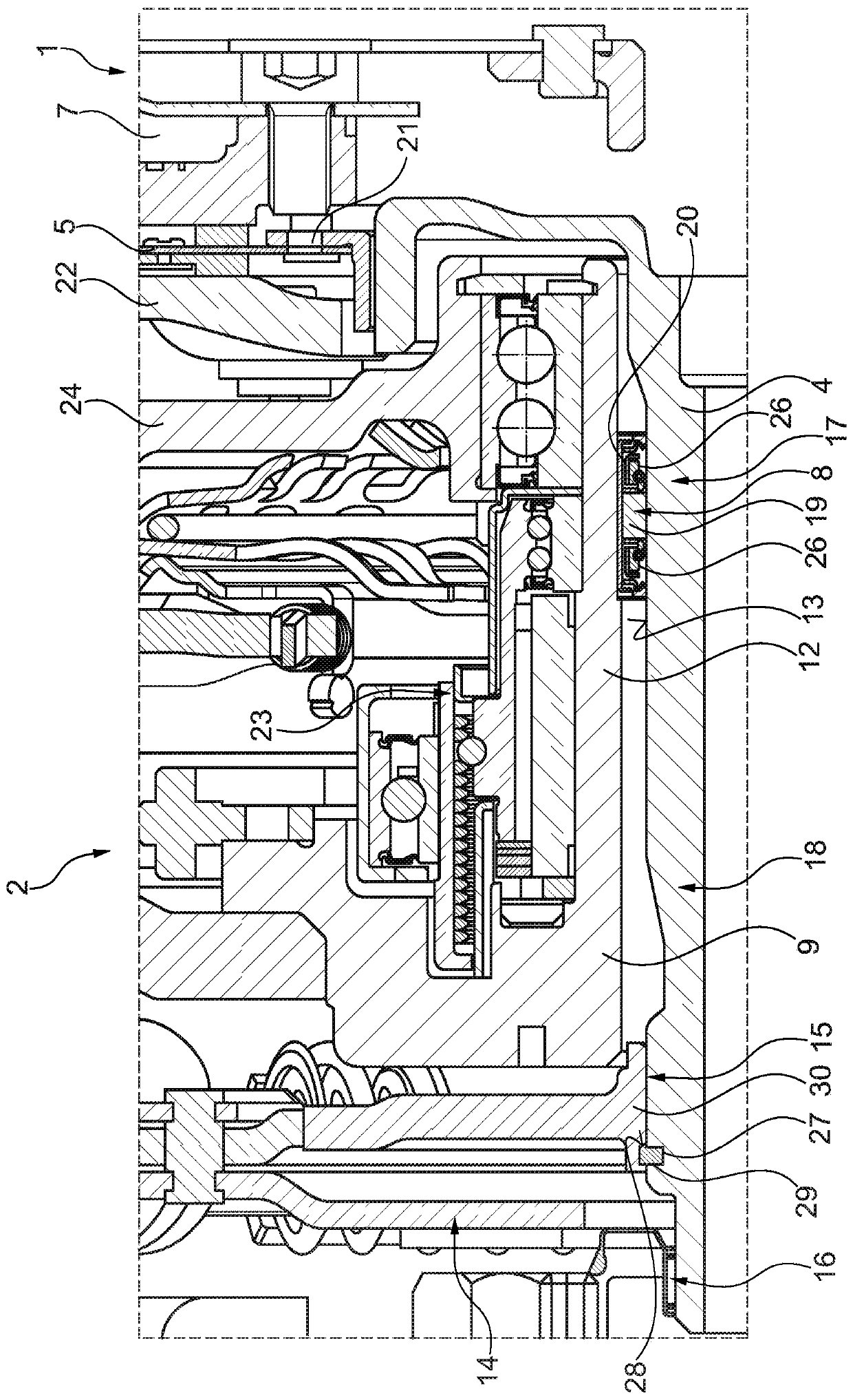
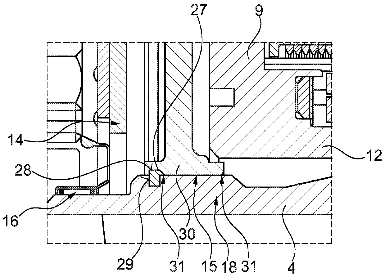
[0027] In two implementations, such as Figure 1 to Figure 3 Shown is always a separating clutch 1 according to the invention for a hybrid module 2 of a motor vehicle, for example a passenger car, a van, a bus or an agricultural vehicle. In this case, the separating clutch 1 always has a centrally arranged countershaft 4 that can be driven by the crankshaft 3 . The separating clutch 1 also has a clutch disc 5 which is connected in a rotationally fixed manner to the countershaft 4 and a counterplate 7 which can be connected to the transmission input shaft 6 . The counterplate 7 is non-rotatably connected to the clutch disk 5 in at least one engaged position of the separating clutch 1 . The separating clutch 1 also has a first rolling bearing 8 which is designed to radially support the countershaft 4 . Furthermore, the carrier element 9 provided for radially supporting the rotor 10 of the electric motor 11 is also supported in a fixed manner relative to the mixing module housi...


PUM


Abstract

The invention relates to a separating clutch (1) for a mixing module (2) of a motor vehicle and a mixing module (2) having such a separating clutch (1) comprising: capable of being driven by a crankshaft (3) Driven intermediate shaft (4); clutch disc (5) connected to the intermediate shaft (4) against relative rotation; counter-pressure plate (7) connectable to transmission input shaft (6), the counter-pressure plate (7) is separated The clutch (1) is non-rotatably connected to the clutch disc (5) in at least one engaged position; at least a first rolling bearing (8) radially supporting the intermediate shaft (4); and a carrier element (9), which is provided for For radially supporting the rotor (10) of the electric motor (11), wherein the first rolling bearing (8) is arranged radially nested between the supporting section (12) of the bearing element (9) and the outer peripheral side of the intermediate shaft (4) (13).

Description

technical field [0001] The invention relates to a separating clutch for a hybrid module of a motor vehicle, such as a passenger car, a van, a bus or an agricultural vehicle, which has an intermediate shaft that can be driven by the crankshaft of the internal combustion engine of the motor vehicle; drehfest) connected clutch disc; a counter-pressure plate that can be connected to the transmission input shaft of a transmission (such as a CVT continuously variable transmission) of a motor vehicle, the counter-pressure plate is connected to the clutch disc in a non-rotatable manner at least in the engaged position of the separation clutch; at least a first rolling bearing radially supporting the intermediate shaft; and a carrier element provided for radially supporting the rotor of the electric motor (and preferably additionally for accommodating the clutch actuating device). The invention also relates to a hybrid module with such a separating clutch. Background technique [00...

Claims


Application Information

Patent Timeline
Patent Type & Authority Patents(China)
IPC IPC(8): B60K6/40F16D28/00F16D23/12F16D13/50H02K7/00B60K6/48
CPCB60K6/40B60K6/48F16D13/50F16D23/12F16D28/00H02K7/006F16D2023/123B60K2006/4825B60K6/387Y10S903/914Y02T10/62B60Y2200/92B60Y2400/424B60Y2400/48F16D13/46F16D2300/22
Inventor 威利·鲁德德尼斯·奥帕林
Owner SCHAEFFLER TECH AG & CO KG
Learn More