
Sensor-incorporated bearing assembly for wheels

a technology of bearing assembly and sensor, which is applied in the direction of instruments, force/torque/work measurement apparatus, transportation and packaging, etc., can solve the problems of uneven load acting on the wheels of the vehicle, insufficient detection of only the rotational speed, and insufficient load uniformity, etc., to achieve simplified structure, reduce the number of components used, and stable

Inactive Publication Date: 2010-06-08
NTN CORP
View PDF6 Cites 15 Cited by
  • Summary
  • Abstract
  • Description
  • Claims
  • Application Information

AI Technical Summary

Benefits of technology

[0009]In view of the foregoing, the present invention has been devised to substantially eliminate the problems and inconveniences and is intended to provide a bearing assembly for a wheel, which is capable of detecting the load acting on the wheel and the rotational speed of the wheel and in which means that may serve as a load sensor and / or a rotation sensor can be installed compactly.
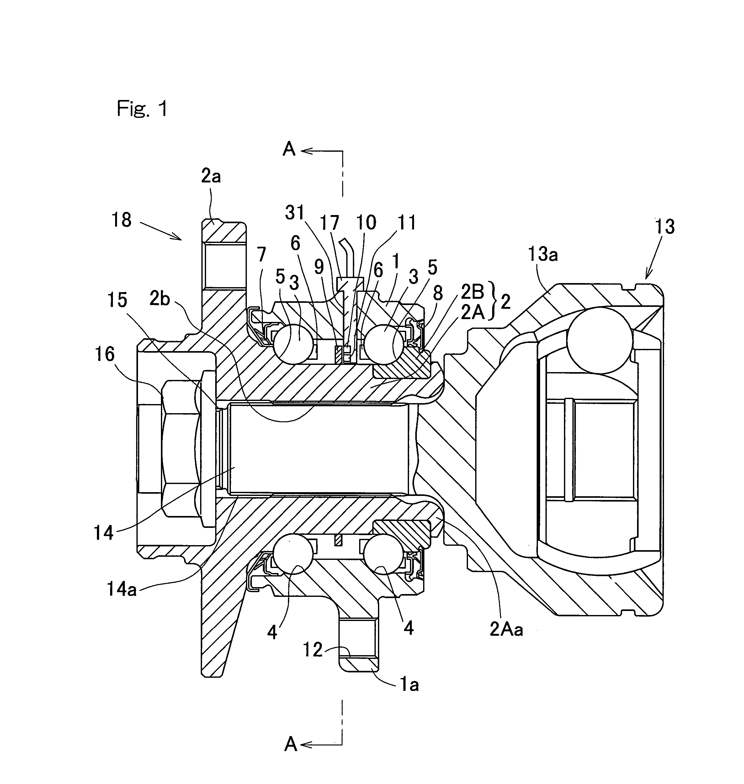
[0016]The displacement sensors, which function as the load sensor and the angle sensor, commonly utilize the same to-be-detected ring and, therefore, as compared with the use of separate to-be-detected rings, a compact construction can be obtained. Also, since the use made of the to-be-detected ring and the displacement sensor, a stable detection is possible.
[0017]As described above, the circuit forming the load sensor and the rotational angle sensor can be compactly installed in the automotive vehicle and the load acting on the wheel and the rotational speed of the wheel can be detected stably.
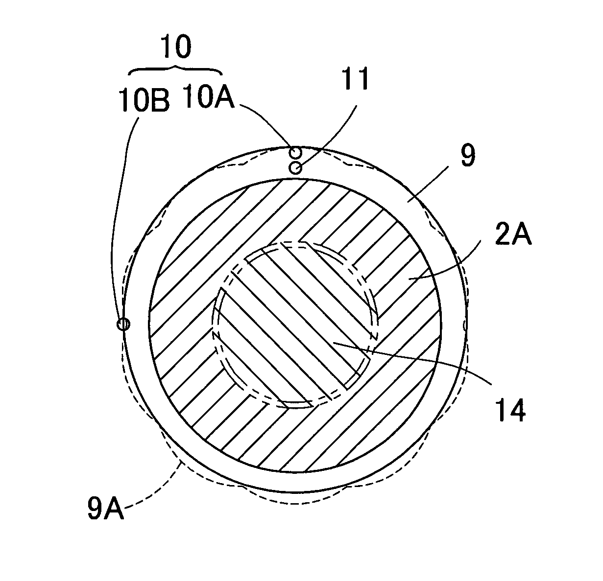
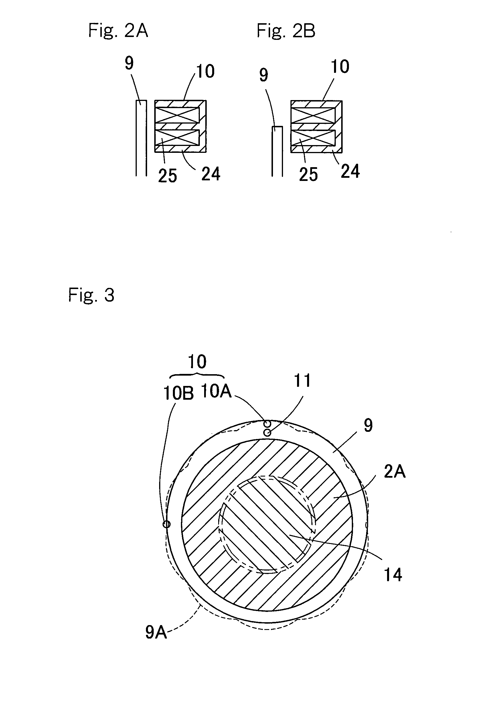
[0021]By arranging the displacement sensors are arranged symmetrically on respective sides of the to-be-detected ring as hereinabove described, a wobbling motion of the to-be-detected ring during rotation thereof and / or a load component occurring when the load acts can be counterbalanced. For example, while the displacement sensor for the detection of the rotational angle can be accompanied by an offset of the signal depending on the magnitude of the bending moment when the latter acts on the inner member, resulting in an adverse influence on the angle detection, positioning of the two displacement sensors on the respective sides of the to-be-detected ring in opposition thereto and taking an average of respective outputs of the two displacement sensors can eliminate the adverse influence which may be brought about by the load. It is to be noted that in this case, even by connecting the respective coiled windings of those two displacement sensors in series with each other, an effect of averaging can be obtained.
[0024]According to this construction, both of the rotation angle of the inner member and the load acting thereon can be detected only from the output of the displacement sensor having the varying facing portion area, and such an advantage can be appreciated that a multi-sensing function can be performed at the same site with a simplified construction despite that the number of component parts used can be reduced and the structure can be simplified. Accordingly, not only can the load sensor and the rotational angle sensor be installed compactly on the automotive vehicle, but the load acting on the wheel and the rotational speed thereof can be detected stably.
[0025]In the present invention, the displacement sensor may be comprised of a magnetic sensor of a winding type. The use of the magnetic sensor of the winding type is advantageous in that the detection of a displacement with the displacement sensor can be achieved stably and with high sensitivity.

Problems solved by technology

While the measures for assuring the running safety of the automotive vehicle hitherto generally employed is practiced by detecting the rotational speed of each of vehicle wheels, it has however been found that the detection of only the rotational speed is insufficient and, therefore, it is increasingly desired that the control on the safety side can be accomplished with the use of any extra sensor signals.
Thus, the load does not always act on the vehicle wheels uniformly at all times during the run of the automotive vehicles.
Also, even in the case of the uneven live load, the loads acting on those wheels tend to become uneven.
However, no suitable space for installation of the load sensor for detecting the load acting on the respective vehicle wheel is available and, therefore, the attitude control through the detection of the load can hardly be realized.

Method used


Image

  • Sensor-incorporated bearing assembly for wheels
  • Sensor-incorporated bearing assembly for wheels
  • Sensor-incorporated bearing assembly for wheels

Examples


third embodiment

[0065]FIG. 10 illustrates in circuit block diagrams, one example of the signal processing circuits forming the detecting circuit 36 for detecting the rotational angle and the load, respectively, based on the respective outputs of the two displacement sensors 10a and 10b according to the In this detecting circuit 36, the output signals from the two displacement sensors 10a and 10b are converted by separate signal processing sections 19 into analog signals, respectively; an average value of those two signals is determined with an angle detecting section 20A; and a result thereof is compared with data in the correction table 21A to provide the rotational angle. Independently thereof, the difference between the two signals that have been converted in the signal processing sections 19 into the associated analog signals is calculated by a load calculating section 22A, and a result of such calculation is then compared with data in the load table 23A to thereby provide the axial load actin...

first embodiment

[0069]Also, although in describing each of the foregoing embodiment reference has been made to the use of the magnetic sensor of winding type for each of the displacement sensors 10 and 11, a sensor system, in which a magnetic loop is formed with a magnet 37, a magnetic detecting element 38 such as, for example, a Hall integrated circuit capable of providing an analog output, and a yoke 39 made of a magnetic material, may be employed such as a fourth preferred embodiment shown in FIG. 11, for each of the displacement sensors 10 and 11 used in the practice of, for example, the It is also to be noted that in FIG. 11, the two displacement sensors 10 and 11 are displaced relative to each other in the circumferential direction.

[0070]The value detected of the angle and the value detected of the load in each of the foregoing embodiments described hereinbefore are incorporated in an ECU (Electric Control Unit) of an automobile and are utilized for the control of the travel stability of the...


PUM


Abstract

A sensor-incorporated wheel support bearing assembly including double rows of rolling elements interposed between respective raceways of outer and inner members opposed to each other, a to-be-detected ring having an eccentric or multangular outer diametric shape provided in the inner member and displacement sensors provided on the outer member confronting the to-be-detected ring. In the bearing assembly, the displacement sensors have facing portion areas, variable and invariable, respectively, arranged with rotation of the to-be-detected ring.

Description

CROSS REFERENCE TO RELATED APPLICATION[0001]This application is based on and claims priority to International Application PCT / JP2005 / 020065 filed Nov. 1, 2005 and Japanese Application No. 2004-323451 filed Nov. 8, 2004, the disclosures of which are hereby incorporated herein by reference.BACKGROUND OF THE INVENTION[0002]1. Field of the Invention[0003]The present invention relates to a sensor-incorporated bearing assembly for wheels, having a built-in device that serves as a load sensor for detecting a load acting on a bearing portion of a wheel and / or an angle sensor for detecting the rotation angle of the wheel.[0004]2. Description of the Prior Art[0005]For safety travel of an automotive vehicle, the use has hitherto been made of a sensor on wheel support bearing assemblies for detecting the respective rotational speeds of wheels. In such a wheel support bearing assembly, it has been suggested in, for example, the Japanese Laid-open Patent Publications No. 2002-340922, published No...

Claims


Application Information

Patent Timeline
Patent Type & Authority Patents(United States)
IPC IPC(8): G01B7/30
CPCB60B27/0005F16C41/007B60B27/0042B60B27/0068B60B27/0084B60B27/0094B60G17/019F16C19/186G01L5/0023G01P3/443G01P3/446B60B27/0026B60G2204/115B60G2206/50B60G2400/208B60G2400/64F16C2326/02
Inventor OZAKI, TAKAYOSHIKOIKE, TAKASHIISHIKAWA, TOMOMI
Owner NTN CORP
Learn More