Eureka AIR delivers breakthrough ideas for toughest innovation challenges, trusted by R&D personnel around the world.

Electric stored energy source

An energy storage unit, electrochemical technology, applied in electrical components, batteries, circuits, etc., can solve problems such as occupying structural space, and achieve the effect of avoiding the loss of energy range

Inactive Publication Date: 2019-09-20
BAYERISCHE MOTOREN WERKE AG
View PDF8 Cites 0 Cited by
  • Summary
  • Abstract
  • Description
  • Claims
  • Application Information

AI Technical Summary

Problems solved by technology

Such cooling / heating systems with their cooling / heating elements occupy valuable installation space within the motor vehicle

Method used


Image

  • Electric stored energy source
  • Electric stored energy source
  • Electric stored energy source

Examples


no. 1 approach

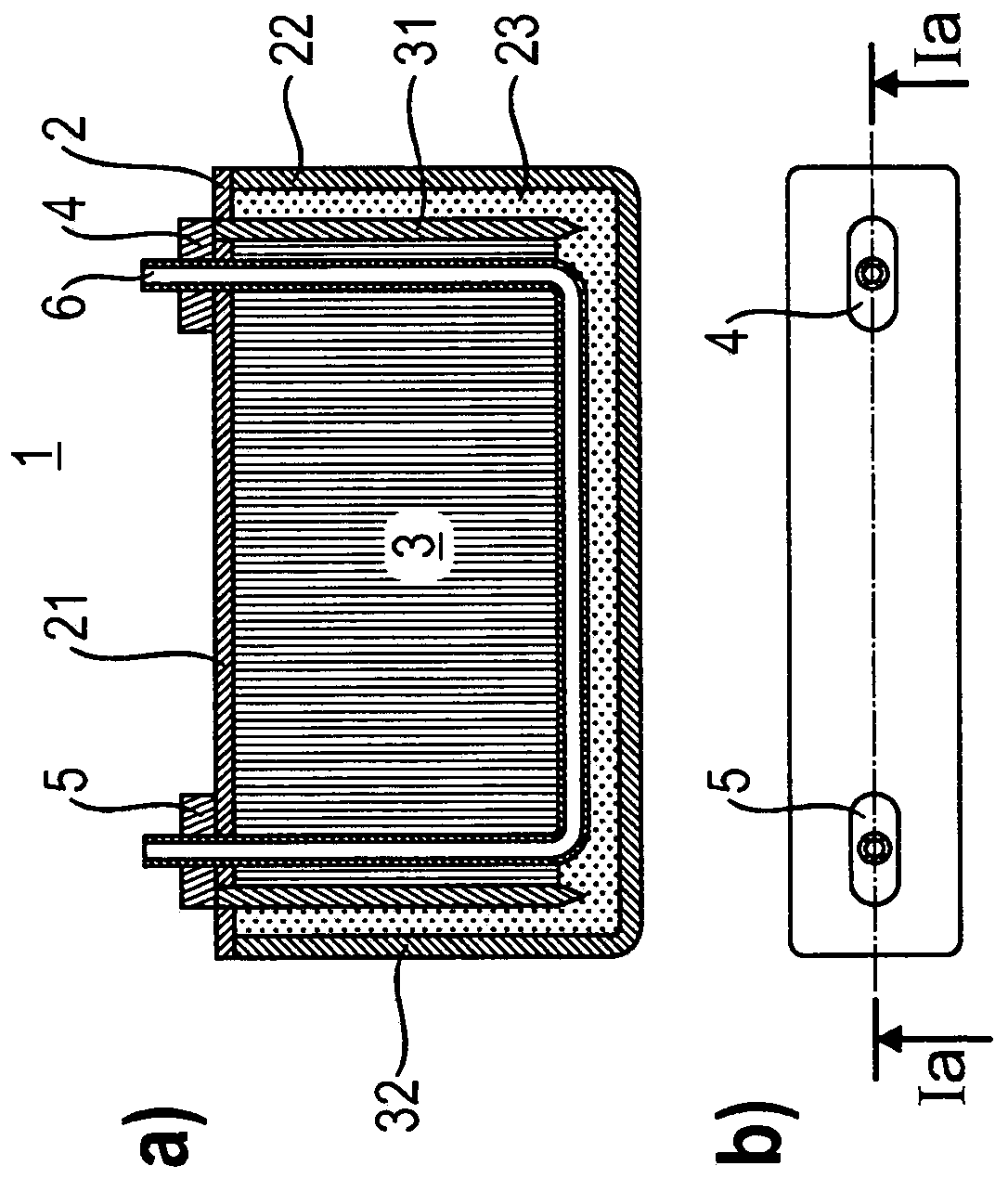
[0044] figure 1 a and b show a preferred first embodiment of the energy storage unit 1 according to the invention, wherein the energy storage unit has a housing 2 .

[0045] The housing 2 preferably comprises a cover 21 and a housing container 22 which is closed by the cover 21 . Lid 21 and / or housing container 22 may be formed from metal or plastic.

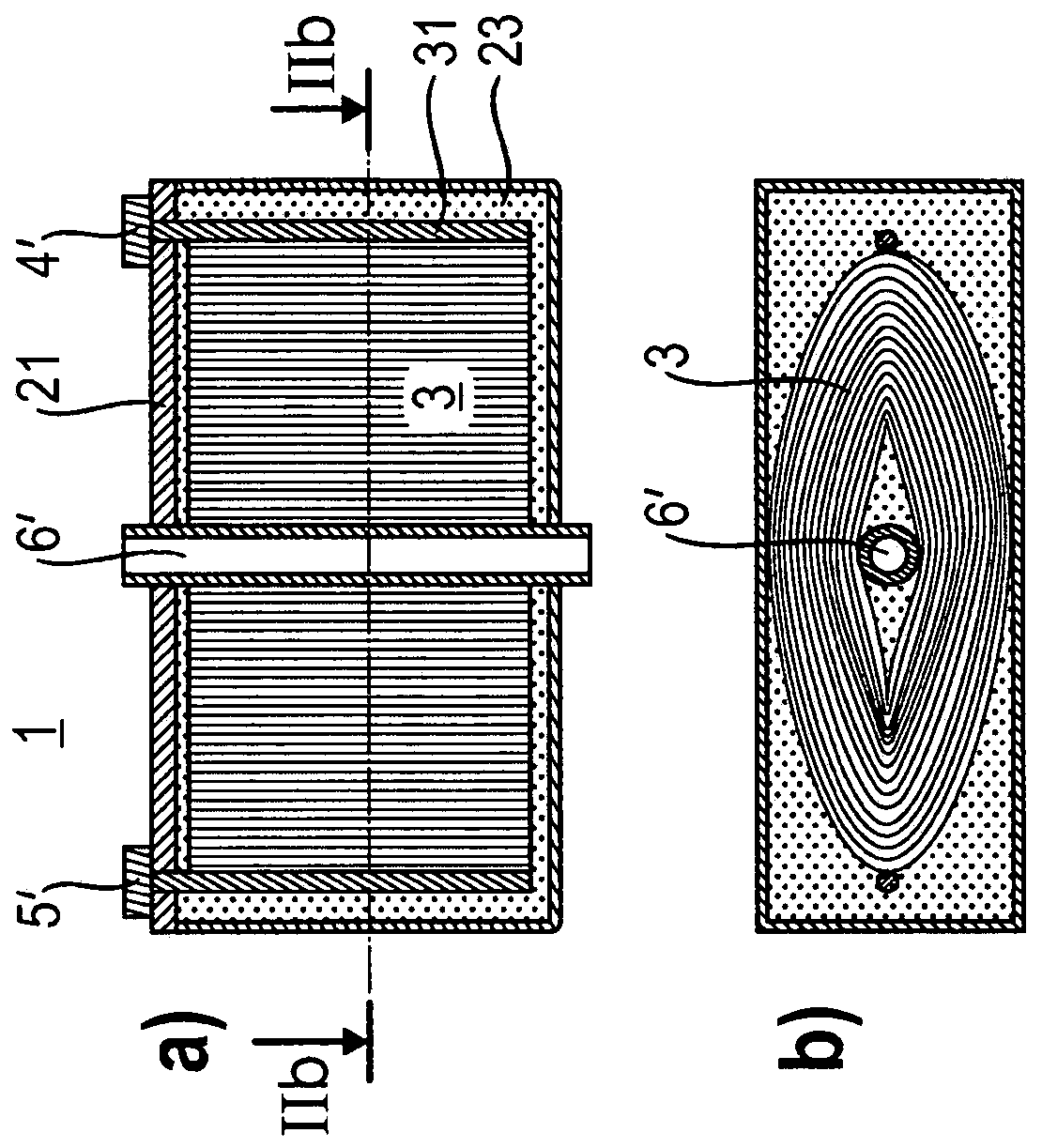
[0046]Housing 2 defines an interior space 23 in which the electrochemical components of energy storage unit 1 according to the invention are accommodated.

[0047] Preferably, the energy storage unit is a lithium-ion energy storage unit and comprises a first electrode strip (transition metal structure) and a second electrode strip (carbon structure), wherein the two electrode strips are separated from one another by a separator. The two electrode strips are wound together with the separator to form the wound structure 3 and are each electrically connected to an electrode 31 , 32 .

[0048] Furthermore, the interior of the hou...


PUM


Abstract

The invention relates to an electric stored energy source (1) for a motor vehicle, which comprises: a housing (2) that defines an inner chamber (23) in which electrochemical components of the energy storage cell (1) are accommodated; and a line (6) extending through the inner chamber and via which a coolant or a heating medium can be guided through the inner chamber (23).

Description

technical field [0001] The invention relates to an electrical energy storage unit for a motor vehicle and to a method for operating an electrical energy storage unit. In particular, the invention relates to such an energy storage unit for powering an electric drive of a motor vehicle. Background technique [0002] Electrical energy storage units are generally known in the prior art and are used in motor vehicles as part of an electrical energy store for electric drives. [0003] In order for the energy storage unit of the electric energy store to function reliably over its service life, it is necessary, for example, to cool the energy storage unit during operation of the motor vehicle or to heat the energy storage unit if necessary during the start-up phase. [0004] To achieve this, cooling / heating systems with corresponding cooling / heating elements that are spatially arranged on the outside of the energy storage unit or the entire energy storage are used in the prior art....

Claims


Application Information

Patent Timeline
Patent Type & Authority Applications(China)
IPC IPC(8): H01M2/02H01M10/48H01M10/654H01M10/6556H01M10/635
CPCH01M10/615H01M10/613H01M10/635H01M10/625H01M10/647H01M10/654H01M10/486H01M10/6556H01M10/6567B60L50/64B60L58/26B60L58/27H01M2220/20B60L2240/36B60L2240/545Y02T10/70Y02E60/10
Inventor T·默滕斯
Owner BAYERISCHE MOTOREN WERKE AG
Why Eureka
Eureka Blog
Learn More