
Synchronous control signal generating circuit

A technology for synchronizing control signals and generating circuits, applied in electrical components, pulse processing, pulse technology, etc., can solve problems such as high cost, complex circuit structure and algorithm, and achieve low cost, good practicability, and high cost performance.

Active Publication Date: 2017-12-01
WENZHOU UNIVERSITY
View PDF6 Cites 6 Cited by
  • Summary
  • Abstract
  • Description
  • Claims
  • Application Information

AI Technical Summary

Problems solved by technology

This method requires a dedicated synchronous signal generator, which has the following problems: ① high cost
[0004] Existing methods for synchronous signal generation either require external equipment, or have complex circuit structures and algorithms, or require communication bus networking and complex algorithms, and have defects in cost, reliability, circuit scale, and software program complexity. relatively prominent

Method used


Image

  • Synchronous control signal generating circuit
  • Synchronous control signal generating circuit
  • Synchronous control signal generating circuit

Examples


Embodiment Construction

[0032] Embodiments of the present invention will be further described below in conjunction with accompanying drawings:

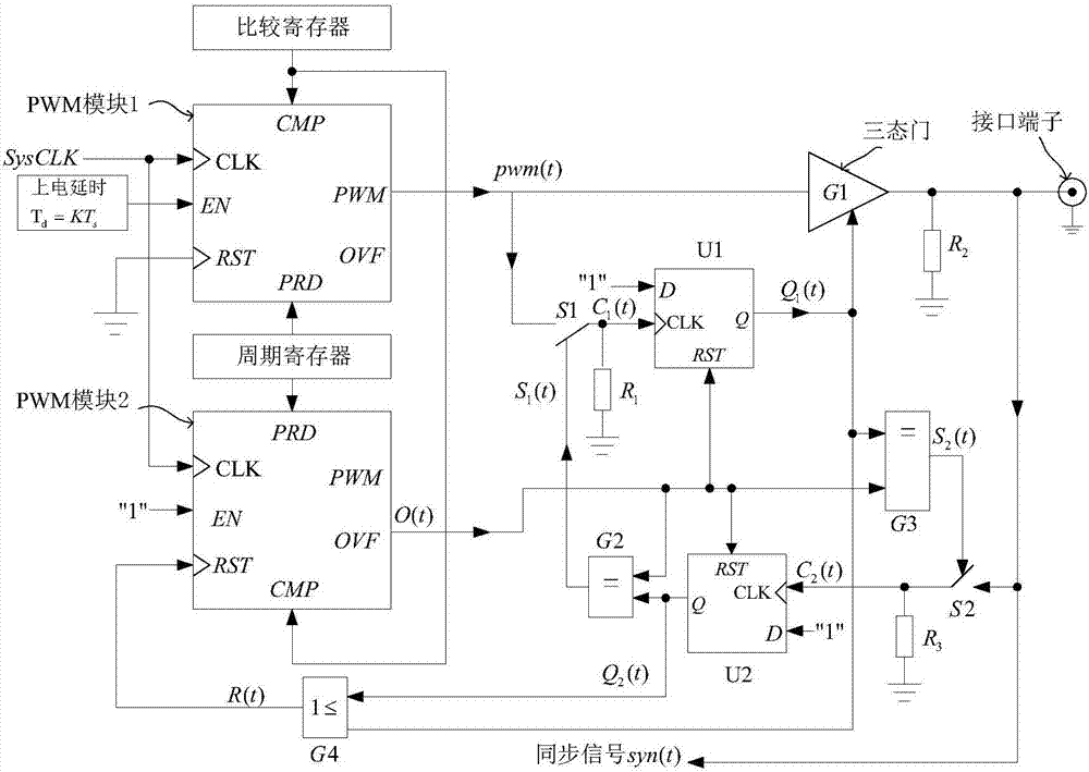
[0033] As shown in the figure, the present invention provides a synchronous control signal generation circuit, which can be directly installed at the controller by means of a plug-in, and connected through a synchronous bus, which includes:

[0034] PWM module 1, output PWM signal pwm(t);

[0035] PWM module 2, output overflow signal pulse O(t), O(t) is used to reset D flip-flops U1 and U2;

[0036] The power-on delay circuit is connected with the PWM module 1 and gives the PWM module 1 a delay T d signal; the power-on delay circuit output delay T d signal, where T d =KT s , where: T s is the period of the output signal pwm(t) of the PWM module 1, and K is a positive integer. When power on, PWM module 1 delays T d start up. For ease of illustration, the present invention assumes that K=1;

[0037] A switch S1 is placed between the PWM module 1 and t...


PUM


Abstract

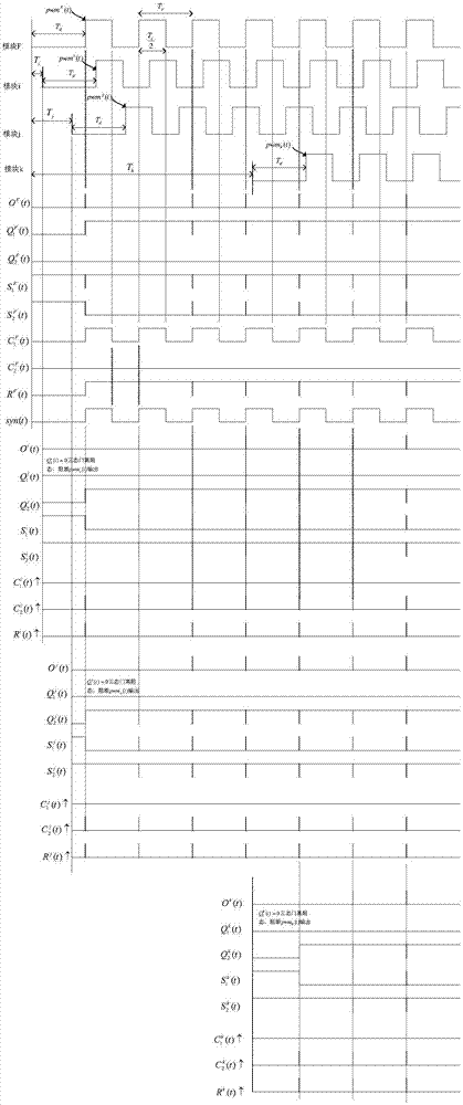
The invention provides a synchronous control signal generating circuit. The generating circuit comprises a PWM module 1, a PWM module 2, a power-on time delay circuit, a D trigger U1, a D trigger U2, an electric control switch S1, an electric control switch S2, a three-state gate G1, an XNOR gate G2, an XNOR gate G3, an OR gate G4, and a synchronous signal syn input-output connection terminal; the generating circuit adopts the non-master-slave and dynamic synchronization scheme, and has higher reliability in comparison with the static master-slave synchronization scheme; a synchronous clock signal source is produced through a competition way in the parallel control, the synchronous clock signal source is from the module with the three-state gate being at the on-state at the earliest in the synchronous control signal generating circuit, so that the synchronous signal source is unique. The generating circuit provided by the invention supports the hot-plugging under the parallel system working condition and cannot lose the synchronous signal. Compared with the synchronous control scheme performed through a communication bus, the synchronous control signal generating circuit has the advantage that the synchronization of the controller can be realized by only using a conductor to connect, the structure is simple and practicability is good.

Description

technical field [0001] The invention relates to a synchronous control signal generating circuit, which is suitable for synchronous control of multiple controllers. Background technique [0002] In the fields of mechanical, electronic, electrical, electric power, computer, chemical and other control, it is usually necessary to perform synchronous control on multiple controllers. For example, the parallel power supply system needs to adjust and control the power module synchronously to achieve high-precision current sharing in the system; in the field of power machinery, when multiple motors are connected in parallel to drive a rotating device, it is necessary to perform synchronous load sharing on the output torque of the motor shaft. Torque lift regulation control. In the field of multi-axis CNC machining, it is necessary to perform synchronous adjustment and control on the controllers with multiple degrees of freedom. Therefore, synchronous control plays an important role...

Claims


Application Information

Patent Timeline
Patent Type & Authority Applications(China)
IPC IPC(8): H03K5/00
CPCH03K5/00Y02B70/10
Inventor 彭志辉李凯周晨潘晓铭刘文文
Owner WENZHOU UNIVERSITY
Learn More