
A cross-type single-pole three-throw switch

A single-pole three-throw switch, cross-shaped technology, applied in the field of radio frequency MEMS, can solve the problems of lower switch yield, difficult process processing, complex switch structure, etc., to improve reliability, avoid ablation and adhesion, and enhance effective The effect of contact

Active Publication Date: 2020-06-09
ZHONGBEI UNIV
View PDF9 Cites 0 Cited by
  • Summary
  • Abstract
  • Description
  • Claims
  • Application Information

AI Technical Summary

Problems solved by technology

For example, the 40th Research Institute of China Electronics Technology Group Corporation discloses a radio frequency coaxial single-pole three-throw switch, which is mainly composed of a radio frequency interface, a radio frequency transmission structure, a driving system, an electromagnetic system and an input control system. J1-J2 is normally closed, so when J1-J3 is on or J1-J4 is on, the coil controlling J1-J2 and the coil of J1-J3 (J1-J4) must be powered at the same time to ensure that J1-J4 is on and J1-J2 is off , the structure of this switch is complicated, and the process is difficult to process, which reduces the yield of the switch

Method used


Image

  • A cross-type single-pole three-throw switch
  • A cross-type single-pole three-throw switch
  • A cross-type single-pole three-throw switch

Examples


Embodiment Construction

[0040] Embodiments of the present invention are described in detail below, examples of which are shown in the drawings, wherein the same or similar reference numerals designate the same or similar elements or elements having the same or similar functions throughout. The embodiments described below by referring to the figures are exemplary only for explaining the present invention and should not be construed as limiting the present invention.

[0041] In the description of the present invention, it should be understood that the orientations or positional relationships indicated by the terms "center", "upper", "lower", "front", "rear", "left", "right" etc. are based on the attached The orientation or positional relationship shown in the figure is only for the convenience of describing the present invention and simplifying the description, and does not indicate or imply that the referred combination or element must have a specific orientation, be constructed and operated in a spec...


PUM


Abstract

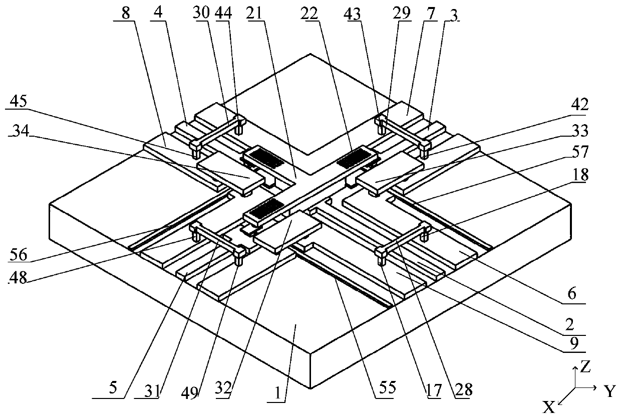
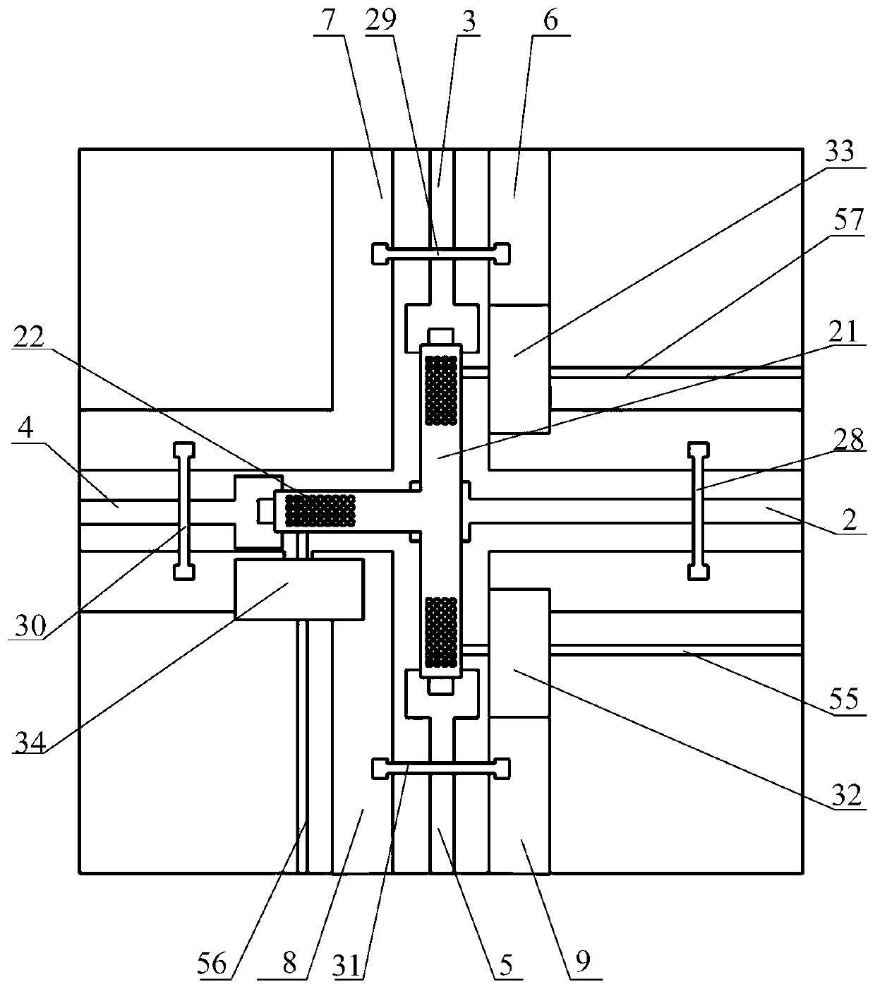
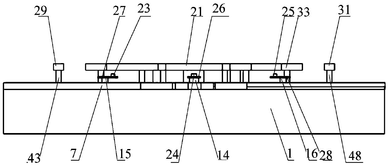
The invention discloses a cruciform single-pole triple-throw switch. A main structure of the switch consists of a substrate, microwave transmission lines, drive electrodes, an upper electrode, a lower electrode, fixed anchor points and air bridges. The microwave transmission lines and the drive electrodes are arranged on the substrate. The upper electrode is a T-shaped straight-plate-type structure. Single, double and triple contacts with elastic beams are used in the lower electrode. In an aspect of mechanics, impact force generated by the upper electrode, which is in rapid pull-down caused by the action of electrostatic force, on the lower electrode can be reduced, a cushioning effect is provided, and thus the contacts and the upper electrode are protected; and in an aspect of electricity, effective contacting can be enhanced, and ablation and adhesion due to weak contacting are avoided. When drive voltage is applied to the first drive electrode, the upper electrode under the action of the electrostatic force is pulled down to contact the contacts, the switch is currently in a conduction state, the upper electrode above the second drive electrode is tilted, an isolation degree of the switch is increased, self-actuation between the upper and lower electrodes is prevented, and the switch life and the microwave performance are also enhanced at the same time.

Description

technical field [0001] The invention belongs to the technical field of radio frequency MEMS, and in particular relates to a cross-type single-pole three-throw switch. Background technique [0002] RF MEMS switch has been a research hotspot in the field of MEMS since the 1990s. RF MEMS single-pole single-throw switch is a basic device for microwave circuit control circuits. Its function is to control the on-off of microwave signals in the transmission system. Used in pulse modulators, attenuators, phase shifters, and T / R components. [0003] At present, the institutions that conduct research on RF MEMS switches mainly include the 13th Institute of China Power Group, the 55th Institute of China Power Group, the Institute of Microelectronics of Tsinghua University, Southeast University, the Institute of Electronics of the Chinese Academy of Sciences, and North University of China. For example, the 40th Research Institute of China Electronics Technology Group Corporation disclo...

Claims


Application Information

Patent Timeline
Patent Type & Authority Patents(China)
IPC IPC(8): H01H59/00
CPCH01H59/0009
Inventor 李孟委王楠刘秋慧张一飞王威
Owner ZHONGBEI UNIV
Learn More