
Monitoring device and method of axial force of shield tunnel joint bolt

A technology for shield tunneling and monitoring devices, which is used to measure torque/torsional force and other directions during tightening, which can solve the problem of extra bolt length and reserved installation space, difficulty in reducing the size of structural safety sensors, thickness of strain gauge pressure sensors, Large size and other problems, to achieve the effect of reduced thickness and size, wide application range, and meet the needs of bolt tightening force measurement

Active Publication Date: 2017-12-01
TONGJI UNIV +1
View PDF6 Cites 12 Cited by
  • Summary
  • Abstract
  • Description
  • Claims
  • Application Information

AI Technical Summary

Problems solved by technology

[0009] The invention patent with the application number 201310235117.3 provides a system and method for measuring the pre-tightening force of the bolt group connection. It proposes to measure the pre-tightening force of the bolt by wearing a cylindrical elastic body with a strain gauge on the bolt, but a similar method is currently used. The strain gauge pressure sensor realized has a large thickness and size, especially when using a large-scale project like a subway shield tunnel, it needs to be anchored at the end of the bolt as a part of the permanent load-bearing structure. The high-intensity load makes it difficult to reduce the size of the sensor, which requires additional bolt length and reserved installation space when the sensor is used in the subway shield tunnel, which is difficult to adapt to the original structural design of the shield tunnel

Method used


Image

  • Monitoring device and method of axial force of shield tunnel joint bolt
  • Monitoring device and method of axial force of shield tunnel joint bolt
  • Monitoring device and method of axial force of shield tunnel joint bolt

Examples


Embodiment Construction

[0049] The present invention will be described in detail below in conjunction with the accompanying drawings and specific embodiments. This embodiment is carried out on the premise of the technical solution of the present invention, and detailed implementation and specific operation process are given, but the protection scope of the present invention is not limited to the following embodiments.

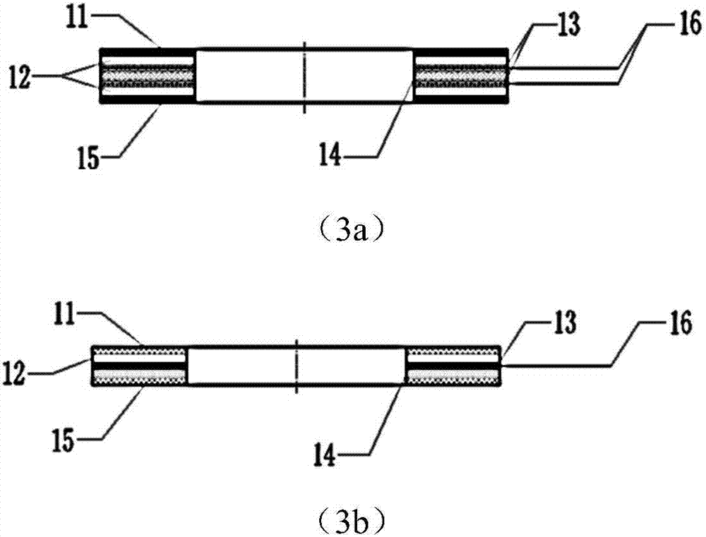
[0050] This embodiment provides a monitoring device and method for the axial force of the shield tunnel joint bolts. The monitoring device includes: a film type bolt axial force sensor 3, which is connected with the shield tunnel joint bolts and is used to withstand the shield tunnel joint bolts. The axial force is directly converted into an electrical signal; the signal processing device 10 is connected with the thin-film bolt axial force sensor 3 during monitoring, and is used to convert the electrical signal transmitted by the thin-film bolt axial force sensor 3 into a readable pres...


PUM

PropertyMeasurementUnit
thicknessaaaaaaaaaa
thicknessaaaaaaaaaa

Abstract

The present invention relates to a monitoring device and method of the axial force of a shield tunnel joint bolt. The device comprises a thin film type bolt axial force sensor which is connected to the shield tunnel joint bolt and is used for directly converting the axial force borne by the shield tunnel joint bolt into an electrical signal, and signal processing equipment which is connected to the thin film type bolt axial force sensor in monitoring and is used for converting the electric signal transmitted by the thin film type bolt axial force sensor into a readable pressure signal. The method comprises a step of carrying out data collection through the thin film type bolt axial force sensor and obtaining the electrical signal of the axial force borne by the joint bolt, and a step of converting the electrical signal into the pressure signal and displaying the pressure signal according to the conversion relation between the electrical signal of the thin film type bolt axial force sensor and the pressure signal. Compared with the prior art, the device and the method have the advantages of a low requirement for an installation space, no damage to a bolt, strong adaptability to a monitoring environment and a wide application range.

Description

technical field [0001] The invention relates to the field of safety monitoring of civil engineering structures, in particular to a monitoring device and method for the axial force of a shield tunnel joint bolt. Background technique [0002] Subway tunnels are mostly constructed by the shield method. The tunnel structure is assembled from prefabricated segments, and the segments are connected by joint bolts. The load-bearing state of the tunnel structure is closely related to the deformation and stress state of the segment joints. The stress state is an important index to evaluate the safety of structures. The subway shield tunnels are mostly located in densely built areas, and the engineering activities around the tunnel are frequent, and the tunnel structure is often damaged under the disturbance of the surrounding engineering. If the axial force of the shield tunnel bolts is monitored, the structural stress status and Its development trend and taking appropriate measures ...

Claims


Application Information

Patent Timeline
Patent Type & Authority Applications(China)
IPC IPC(8): G01L5/24
CPCG01L5/24
Inventor 苏文德张竹清游连章林俪昕刘学增赖浩然郭乔堃
Owner TONGJI UNIV
Learn More