Diagnosis method for desorption flow of high-load desorption pipeline of carbon tank

A technology of desorption flow and diagnosis method, applied in the field of diagnosis of emission system, can solve the problems of inappropriate electrical equipment, limited interior space of vehicles, unfavorable vehicle lightweight, etc., so as to meet the requirements of lightweight, reduce costs, and simplify the system. effect of structure

Active Publication Date: 2017-12-01
SAIC MOTOR
View PDF8 Cites 21 Cited by
  • Summary
  • Abstract
  • Description
  • Claims
  • Application Information

AI Technical Summary

Problems solved by technology

[0004] In the prior art, it is usually necessary to install a pipeline pressure sensor 8 at the A end of the venturi tube 4, to open the canister electromagnetic valve 3 during detection, and to diagnose the negative pressure state of the pipeline pressure sensor 8 when the canister shut-off valve 6 is closed. Judgment: Although this judgment method is relatively reliable, the interior space of the vehicle is limited, and the electrical equipment should not be too many. The additional pipeline pressure sensor 8 will also involve wiring interference, sealing, safety and other issues, which is not conducive to the lightweight of the vehicle. demand, and will further increase the cost of the vehicle

Method used


Image

  • Diagnosis method for desorption flow of high-load desorption pipeline of carbon tank
  • Diagnosis method for desorption flow of high-load desorption pipeline of carbon tank

Examples


Embodiment

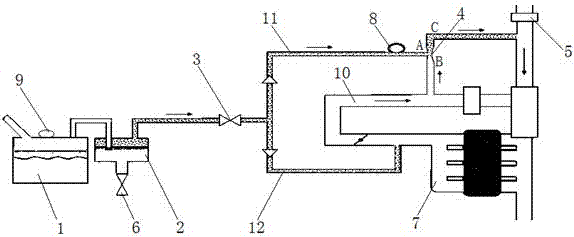
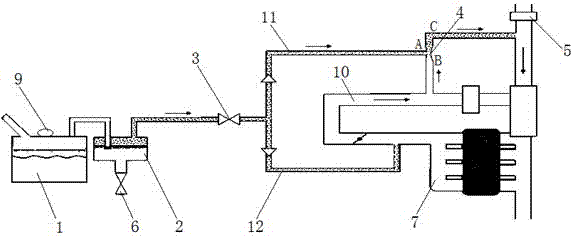
[0026] Such as figure 2 As shown, a method for diagnosing the desorption flow rate of the carbon canister high-load desorption pipeline,

[0027] Select a vehicle with intact desorption pipeline as the standard vehicle,

[0028] First, check the standard vehicle. The specific inspection method is to start the vehicle, close the carbon tank solenoid valve 3 at the same time, and open the carbon tank stop valve 6. At this time, there is no air flow through the fuel tank 1 and the venturi tube 4, and the fuel tank 1 and the carbon tank 2 Connect with the atmosphere, wait for a certain period of time, read the data of the fuel tank air pressure sensor 9 in the fuel tank 1, and compare it with the ambient pressure, such as the fuel tank pressure P obtained from the fuel tank air pressure sensor 9 1 = ambient pressure P 0 , it means that the fuel tank pressure sensor 9 and / or the gas circuit of the fuel tank are normal; if the fuel tank pressure P 1 ≠ atmospheric pressure P 0 ,...


PUM


Abstract

The invention relates to the field of vehicle emission, in particular to a diagnosis method for an emission system. A diagnosis method for desorption flow of a high-load desorption pipeline of a carbon tank comprises the following steps: selecting a vehicle with an intact desorption pipeline as a standard vehicle, starting the vehicle, opening an electromagnetic valve of the carbon tank, and closing a stop valve of the carbon tank; waiting for a certain time, and acquiring the vacuum degree in an oil tank; testing repeatedly under each residual fuel amount to obtain a function of the vacuum degree and the residual fuel amounts; and when the diagnosis is performed in actual travelling of the vehicle, comparing a vacuum degree threshold value obtained according to the actual residual fuel amount and the function with the actual vacuum degree to realize the diagnosis of the high-load desorption pipeline. In step S1, the vehicle is started and kept in an idle state. According to the diagnosis method, the diagnosis of the desorption flow of the high-load desorption pipeline is completed by using an existing sensor and an existing executor; and a pressure sensor is not required to be mounted in a Venturi pipe, so that the cost is reduced, meanwhile, the matched wiring harness layout of the sensor is also simplified, the system structure is simplified, and the requirement on light weight of a compact vehicle is met better.

Description

technical field [0001] The invention relates to the field of vehicle emission, in particular to a method for diagnosing an emission system. Background technique [0002] With the upgrading of emission regulations from China V to China VI, the technical requirements for the evaporation system are increasing day by day. The requirements are mainly as follows: 1) newly added fuel system leakage diagnosis; 2) stricter control requirements for evaporative emissions; 3) New requirements for the control of emissions during refueling; 4) New diagnosis for whether there is desorption flow in the canister desorption pipeline; [0003] Such as figure 1 , usually on a vehicle with a gasoline engine, especially a vehicle with a supercharger engine, it will be equipped with two carbon canister desorption pipelines, one of which is connected to the intake manifold 7 via the carbon canister electromagnetic 3, That is the so-called low-load desorption pipeline 12, when the gas pressure in ...

Claims


Application Information

Patent Timeline
Patent Type & Authority Applications(China)
IPC IPC(8): F02M25/08F02D41/22
CPCF02D41/22F02D2041/225F02M25/08Y02T10/40
Inventor 毛俊培朱建伟顾萌君
Owner SAIC MOTOR
Why Eureka
Try Eureka