An engine solenoid valve driving circuit and its control method

A technology of solenoid valve driving and engine controller, applied in the direction of engine control, electrical control, machine/engine, etc., can solve the problems of poor safety performance and stability, complicated circuit structure and driving mode, etc., to achieve stable performance and range of use. Extensive, easy-to-control effects

Active Publication Date: 2015-09-30
常州易控汽车电子股份有限公司
View PDF5 Cites 0 Cited by
  • Summary
  • Abstract
  • Description
  • Claims
  • Application Information

AI Technical Summary

Problems solved by technology

[0006] The purpose of the present invention is to overcome the defects of complex circuit structure and driving mode, poor safety performance and stability performance in the current high-end and low-end drive circuits of the solenoid valve drive circuit, and provide a simple structure, stable performance, and high safety. High engine solenoid valve drive circuit

Method used


Image

  • An engine solenoid valve driving circuit and its control method
  • An engine solenoid valve driving circuit and its control method
  • An engine solenoid valve driving circuit and its control method

Examples


Embodiment

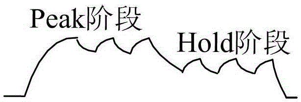
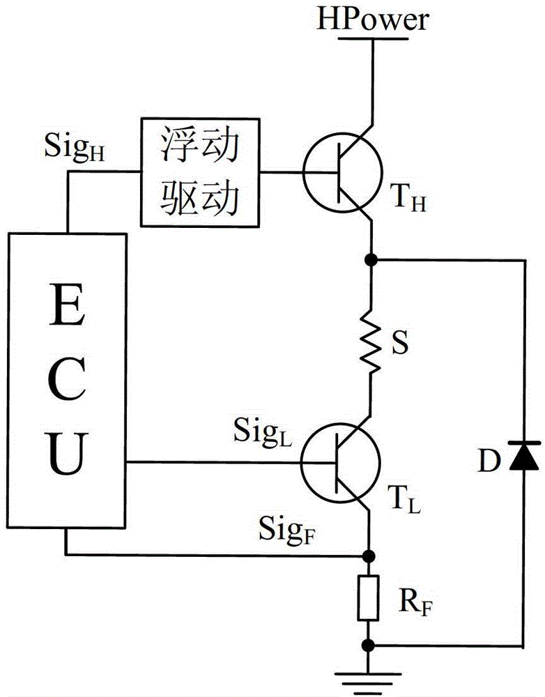
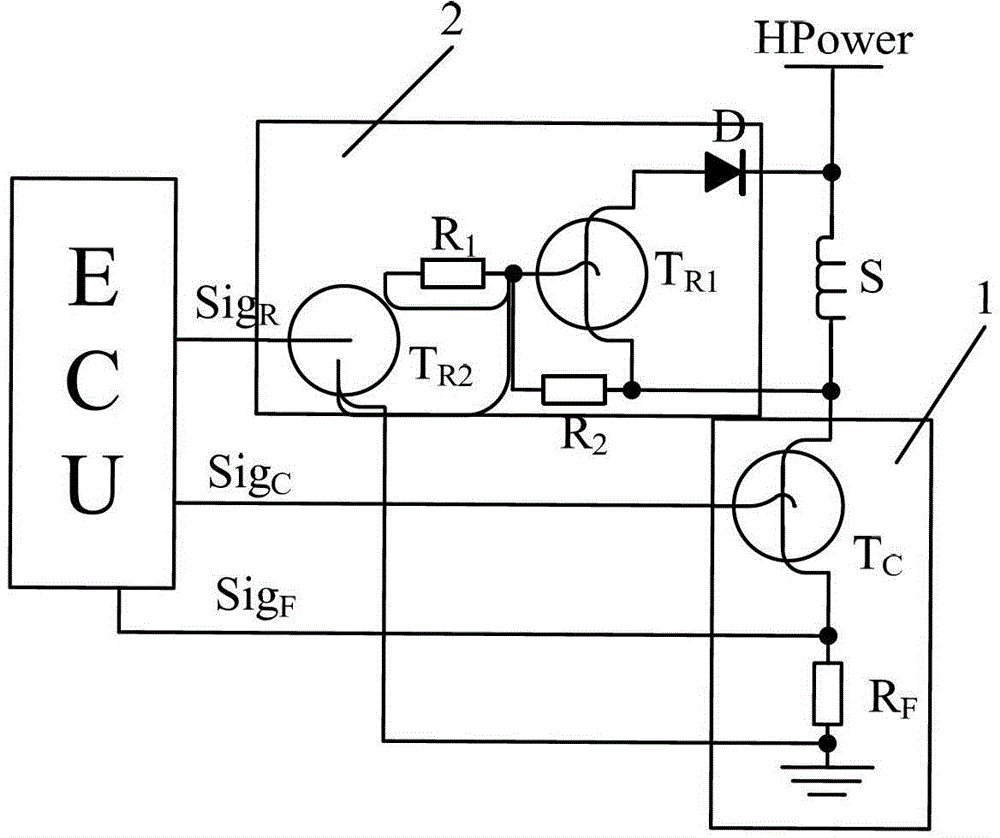
[0030] figure 1 , 2 The content shown is the drive circuit structure and its corresponding Peak & Hold drive current waveforms currently used by people. image 3 It is a structural schematic diagram of the engine solenoid valve driving circuit of the present invention, which is composed of a control triode circuit 1 and a freewheeling protection circuit 2 . Among them, S is the solenoid valve controlled by the drive circuit of the present invention, referred to as "controlled solenoid valve S"; ECU is the engine controller, and it has multiple input terminals and output terminals.

[0031] The control triode circuit 1 is composed of a sampling resistor RF and an N-type triode TC. When connected, the gate and source of the triode TC are directly connected to the ECU to receive the control signal SigC and the driving current sampling of the ECU respectively. Signal SigF. One end of the sampling resistor RF is grounded, and the other end is connected to the source of the triod...


PUM


Abstract

The invention discloses an engine magnetic valve drive circuit. The engine magnetic valve drive circuit is characterized by mainly comprising a triode control circuit (1) and a follow current protective circuit (2), wherein the triode control circuit (1) is connected with an engine controller and the follow current protective circuit (2) is respectively connected with the triode control circuit (1) and the engine controller. The engine magnetic valve drive circuit is composed of a small number of common components, not only is simple in structure, but also stable in performance, and can completely overcome the defect that a floating drive circuit needs to be adopted in a traditional high-low-side circuit, and therefore complexity and cost of the drive circuit are obviously lowered.

Description

technical field [0001] The invention belongs to the field of electronically controlled engine control systems, and specifically refers to an engine solenoid valve drive circuit and a control method thereof. Background technique [0002] At present, in electronically controlled engine control systems such as diesel injector solenoid valves, gasoline injector solenoid valves, and natural gas engine injector solenoid valves, the driving circuits of related solenoid valves mostly use the following control methods: First, According to the crankshaft and camshaft signals, relevant information such as engine speed and phase position are obtained, and control parameters such as fuel injection quantity and fuel injection advance angle are calculated, and then the actuators such as the fuel injector drive circuit are controlled to drive the circuit according to the phase position to realize Control of the engine. In this control mode, the solenoid valve driving circuit can control th...

Claims


Application Information

Patent Timeline
Patent Type & Authority Patents(China)
IPC IPC(8): F02D41/20F02D41/30
Inventor 张科勋郝守刚李中褚全红白思春
Owner 常州易控汽车电子股份有限公司
Why Eureka
Try Eureka