
Can cleaning and air-drying device

An air-drying device and canned technology, which is applied in the directions of drying gas arrangement, drying, drying machine, etc., can solve the problems of only washing the side wall and upper surface of the tank body, unable to clean the bottom of the tank body, and incomplete cleaning, etc. Achieve the effect of reducing plant area, saving energy and avoiding wear and tear

Inactive Publication Date: 2017-12-01
重庆乐嚼食品有限公司
View PDF6 Cites 6 Cited by
  • Summary
  • Abstract
  • Description
  • Claims
  • Application Information

AI Technical Summary

Problems solved by technology

Using this method to wash the tank body has the following defects: because the cans are placed on the conveyor belt, the hot water spray device can only wash the side wall and upper surface of the tank body, but cannot clean the bottom of the tank body, making the cleaning incomplete

Method used


Image

  • Can cleaning and air-drying device
  • Can cleaning and air-drying device
  • Can cleaning and air-drying device

Examples


Embodiment 1

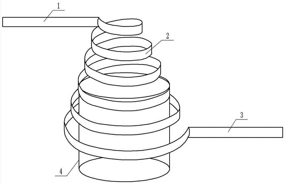
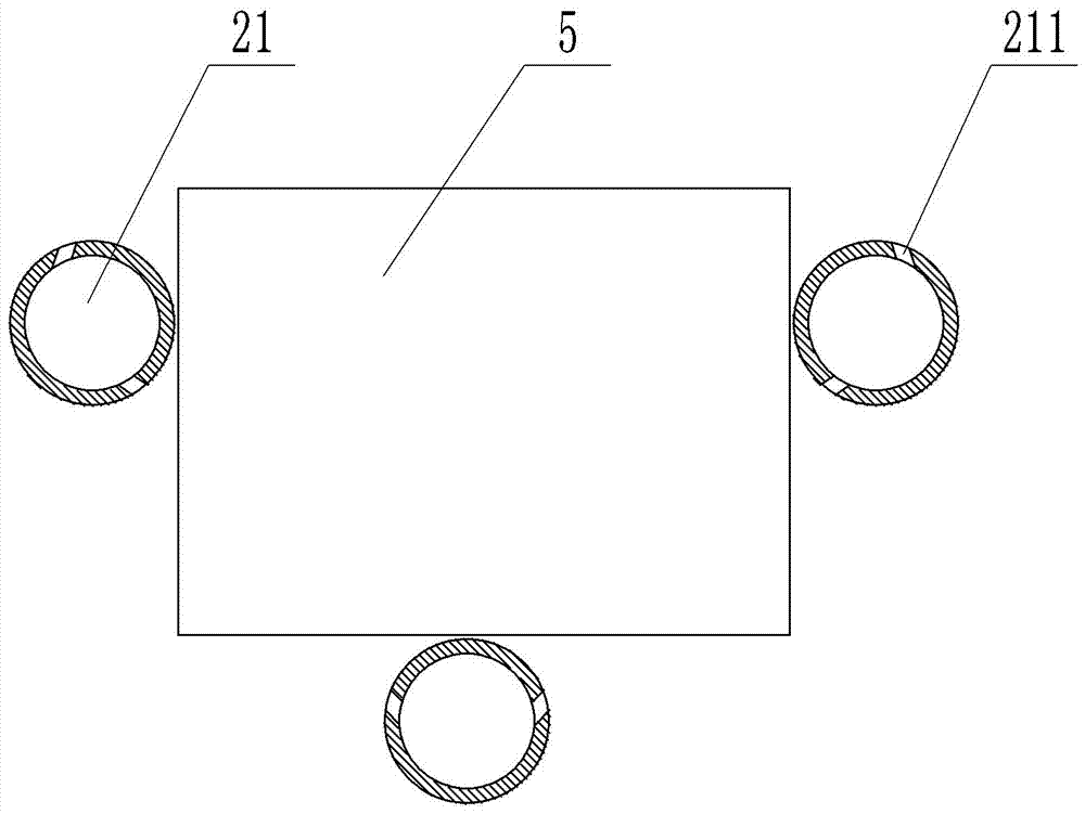
[0022] Such as figure 1 As shown, the can washing and air-drying device includes an upper transmission device 1, a spiral track 2 and a lower transmission device 3 from top to bottom, the upper transmission device 1 is located on the side of the entrance above the spiral track 2, and the lower transmission device 3 is located on the spiral track 2 side of the lower exit. Such as figure 2 As shown, the spiral track 2 includes 3 pipes 21, the 3 pipes 21 are respectively located on the left and right sides and the bottom of the can 5 to be transported, and the 3 pipes 21 form a whole by welding, and the 3 pipes 21 are used for supporting and Canned food 5 is conveyed; the spiral track 2 is designed as a spatial spiral as a whole, and the diameter of the spiral increases gradually from top to bottom. The spiral track 2 includes an upper part and a lower part, and a barrel-shaped support 4 is arranged at the junction of the upper part and the lower part. A drain valve is install...

Embodiment 2

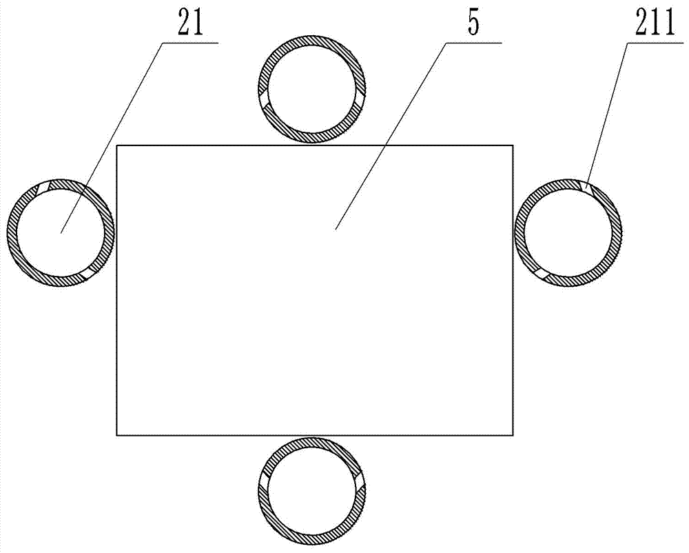
[0025] The difference between embodiment 2 and embodiment 1 is that the spiral track 2 of embodiment 2 includes four pipes 21, which are respectively located on the four sides of the cans 5 to be transported, up, down, left, and right, as image 3 shown. There are four pipelines 21, and the canned food 5 will not be thrown out of the spiral track 2 during the transmission process, which ensures the reliability and safety of the transportation.


PUM


Abstract

The invention belongs to the technical field of cleaning hollow articles through special methods or equipment and particularly discloses a can cleaning and air-drying device comprising an upper conveying device, a lower conveying device and a spiral rail. The spiral rail comprises a plurality of pipelines. The at least one pipeline is arranged on each of the left and right sides of the spiral rail. The spiral rail is in a spatial spiral shape, and the spiral diameter of the spiral rail is gradually increased from top to bottom. The upper conveying device is located on the upper inlet side of the spiral, and the lower conveying rail is located on the lower outlet side of the spiral rail. The spiral rail comprises an upper part and a lower part. A barrel-shaped supporting column is arranged in the connecting position of the upper part and the lower part. A plurality of water spraying holes for cleaning the surfaces of a can are formed in pipelines of the upper part of the spiral rail correspondingly, and a plurality of air holes opposite to the conveyed can are formed in pipelines of the lower part of the spiral rail correspondingly. By using the can cleaning and air-drying device to clean the can, the surfaces of the can be comprehensively cleaned, and besides, drops on the surfaces of the can are also capable of being spin-dried through hot air and the special structure of the spiral rail.

Description

technical field [0001] The invention belongs to the technical field of cleaning hollow objects with a special method or equipment, and in particular relates to a can cleaning and air-drying device. Background technique [0002] With the improvement of residents' living standards, travel and tourism continue to increase, and food consumption concepts and methods are quietly changing. Many families are trying to liberate themselves from the kitchen to reduce oil fume pollution and housework. Canned food is adapting to people's daily needs due to its convenience, sanitation and easy storage, and is increasingly popular. In the process of food processing, in order to improve hygiene standards, it is necessary to clean various objects including raw materials, processing equipment, packaging containers, packaged products, processing sites and production personnel. Cleaning is an important measure to ensure and improve food quality and safety from the source. The finished canned ...

Claims


Application Information

Patent Timeline
IPC IPC(8): B08B9/30F26B15/26F26B21/00
CPCB08B9/30F26B15/26F26B21/004
Inventor 肖明孝
Owner 重庆乐嚼食品有限公司
Learn More