Shoe sole structure wearable in four seasons based on exhaust holes

A technology of air vents and air holes, which is applied in the field of four-season available sole structures, can solve the problems of being unsuitable for large-scale production, high cost, and low cost, and achieve the effects of low production cost, simple structure, and improved general performance

Inactive Publication Date: 2017-12-01
成都卡美奇鞋业有限公司
View PDF4 Cites 0 Cited by
  • Summary
  • Abstract
  • Description
  • Claims
  • Application Information

AI Technical Summary

Problems solved by technology

[0004] The technical problem to be solved by the present invention is: the existing shoe uppers and soles can be disassembled to achieve winter and summer wearable shoes, which have the problems of high cost and not suitable for large-scale production. Type sole structure, which can effectively realize the change of the ventilation and non-ventilation state inside the shoe without disassembling between the upper and the sole, suitable for large-scale production, and low cost

Method used


Image

  • Shoe sole structure wearable in four seasons based on exhaust holes
  • Shoe sole structure wearable in four seasons based on exhaust holes

Examples


Embodiment 1

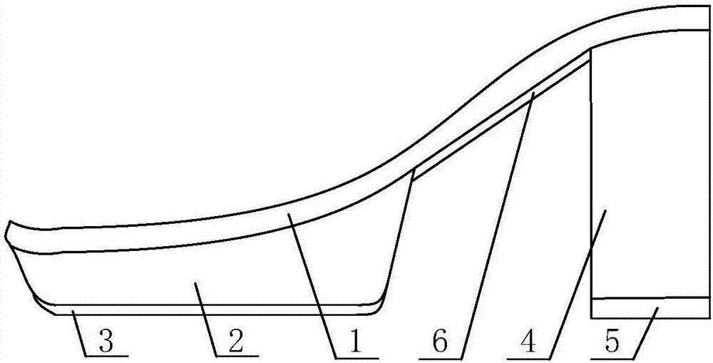
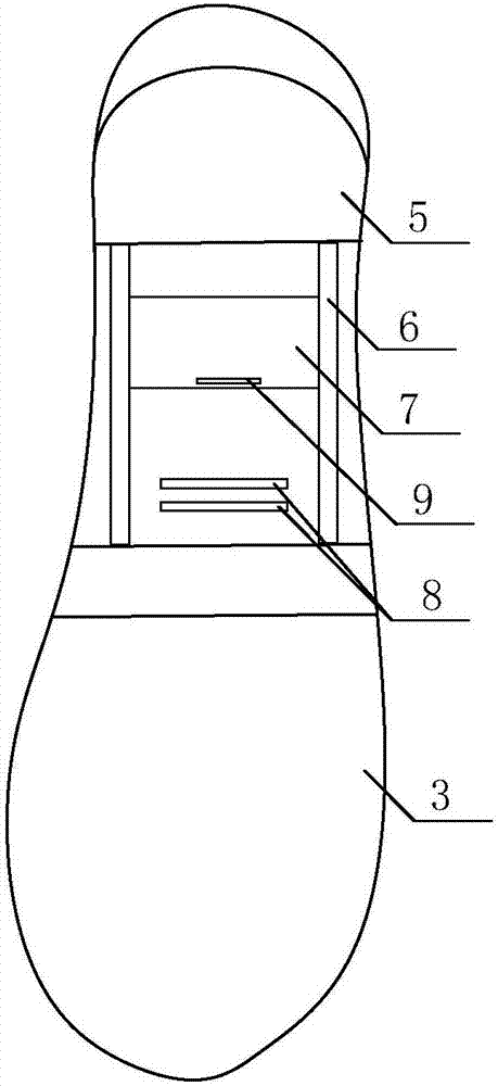
[0024] A four-season sole structure based on air vents, such as Figure 1-Figure 2 As shown, it includes a midsole 1, a waterproof platform 2 arranged at the front position of the midsole 1, an outsole 3 arranged at the bottom of the waterproof platform 2, a heel 4 arranged at the rear position of the midsole 1, and a heel 4 arranged at the heel 4 The sky skin at the bottom 5.

[0025] The waist position of the midsole 1 is provided with an air vent 8 that runs through the midsole 1, and fixed chute 6 is provided on both sides of the bottom surface of the midsole 1 below the air vent 8, and the fixed chute 6 is also provided with a useful It is used to block the sliding baffle plate 7 of the ventilation hole 8.

Embodiment 2

[0027] The difference between this embodiment and Embodiment 1 is that the structure of the air vent 8, the fixed chute 6 and the sliding baffle 7 is optimized, and the specific settings are as follows:

[0028] The air holes 8 are long strips, the length is 1 / 2-2 / 3 of the width of the midsole 1, and the width is 2-5mm. In this embodiment, the number of the air holes 8 is two, and the width of each air hole 8 is 2-3 mm.

Embodiment 3

[0030] The difference between this embodiment and Embodiment 1 is that in this embodiment, the structure at the position of the fixed chute 6 is optimized, and the specific settings are as follows:

[0031] The fixed chute 6 is composed of two symmetrical concave pieces opposite to each other in the opening direction. One side of the sliding baffle 7 extends into one of the concave parts, and the opposite side of the sliding baffle 7 extends into the other concave part; the remaining two sides of the sliding baffle 7 are provided with wind-blocking strips . The concave part is made of stainless steel. The wind blocking strip is made of rubber material.

[0032] The bottom end of the midsole 1 is provided with a groove, and the fixed sliding groove 6 is installed in the groove. The sliding baffle 7 is provided with a bump that is convenient for manually moving the position of the sliding baffle 7 .


PUM


Abstract

The invention discloses a shoe sole structure wearable in four seasons based on exhaust holes. The structure solves the problems that in existing modes of assembling shoe uppers and shoe soles, shoes wearable in both winter and summer are high in cost and unsuitable for mass production. The structure comprises an insole, a waterproof platform arranged at the front portion of the insole, an outsole arranged at the bottom end of the waterproof platform, a heel arranged at the rear portion of the insole and a heel lift arranged at the bottom end of the heel; vent holes running through the insole are formed in the flank portion of the insole, fixed sliding grooves are formed in the two sides of the bottom surface of the insole below the vent holes, and a sliding baffle for shielding the vent holes is also arranged on the fixed sliding grooves. The shoe sole wearable in four seasons has the advantages of being wearable in both winter and summer, suitable for mass production, low in cost and the like.

Description

technical field [0001] The invention belongs to the field of shoes, and in particular relates to a four-season shoe sole structure based on air vents. Background technique [0002] Most of the shoes suitable for wearing in winter and summer in the prior art have changed the traditional and inherent concept that people think that the upper and the sole of the shoes can only be fixedly connected as one. Snap buttons and other devices that are convenient for assembly and disassembly are designed to provide shoes with replaceable uppers that can be easily removed or installed. After the vamp is removed, the purpose of ventilation and ventilation can be easily achieved, and the ultraviolet rays can fully sunbathe the inside of the shoe, so as to achieve the purpose of disinfection and sterilization, and prevent the occurrence of athlete's foot. [0003] However, the structure is relatively complicated, the cost is high, and it is not suitable for mass production. Contents of t...

Claims


Application Information

Patent Timeline
Patent Type & Authority Applications(China)
IPC IPC(8): A43B13/14A43B7/10
CPCA43B13/14A43B7/087A43B7/10
Inventor 赖金元
Owner 成都卡美奇鞋业有限公司
Why Eureka
Try Eureka