
Submersible power generation platform

A platform and generator technology, applied in hydroelectric power generation, ocean energy power generation, engine components, etc., can solve problems such as impossible installation and repair, slow flow rate, and difficult installation of blade tilt

Inactive Publication Date: 2017-11-28
李东仁
View PDF9 Cites 4 Cited by
  • Summary
  • Abstract
  • Description
  • Claims
  • Application Information

AI Technical Summary

Problems solved by technology

Specifically, the disadvantage of the pillar type is that it requires considerable installation costs, and if the blades are installed in deep water, the power generation efficiency will be reduced due to the slow flow rate.
In the case of the bottoming type, the weight of the large-scale structure is very heavy, so that when the structure is placed on the terrain with strong ocean currents or the structure is fished out for repairs, large-scale equipment like a crane is required, so the operation is complicated. Significant costs are required in terms of equipment and maintenance
In addition, in the tethered type, the floating structure is fixed by the rope, and the structure may lose its balance depending on the buoyancy of the structure, the weight of the structure and the rope, the flow of seawater, etc.
In addition, in the initial stage of installation, the lower part of the blade is submerged in water and the upper part is floating in the air. At this time, the seawater flows concentratedly in the lower part of the blade, and the installation of the blade is difficult due to inclination, and the possibility of accidents also increases.
In addition, with the increase in the size of structures, it is impossible to perform installation and repair work without large-scale equipment, and even a slight imbalance of forces may cause a large-scale accident
In addition, in order to repair and maintain the structures placed in the water, divers need to wear diving suits to carry out underwater operations, so the efficiency of the work is drastically reduced, and there is no efficiency in terms of repair costs and repair time.
Not only that, but if the blade touches the bottom surface due to a reduction in buoyancy or failure, the blade will be damaged, and if the flow velocity suddenly increases due to a typhoon, etc., the blade cannot be avoided, and the blade will inevitably be damaged.

Method used


Image

  • Submersible power generation platform
  • Submersible power generation platform
  • Submersible power generation platform

Examples


Embodiment Construction

[0062] The purpose, specific advantages and novel features of the present invention will be more clearly understood through the following detailed description and preferred embodiments associated with the accompanying drawings. In this specification, reference numerals are given to constituent elements in each drawing, and it should be noted that the same constituent elements are assigned the same numerals as much as possible even if they are shown in different drawings. In addition, terms such as "first" and "second" are used to distinguish one constituent element from other constituent elements, and the constituent elements are not limited to the terms. Hereinafter, when describing the present invention, detailed descriptions of related known technologies that may unnecessarily obscure the gist of the present invention will be omitted.

[0063] Hereinafter, preferred embodiments of the present invention will be described in detail with reference to the drawings.

[0064] f...


PUM


Abstract

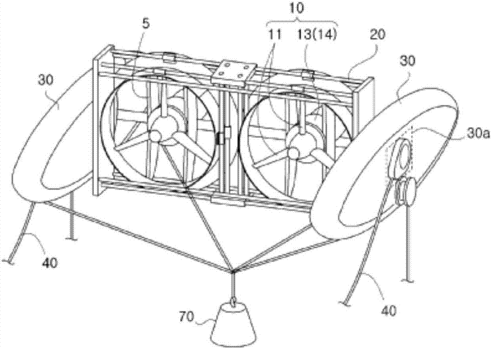
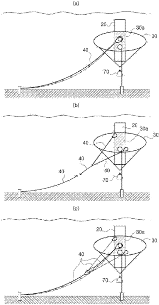
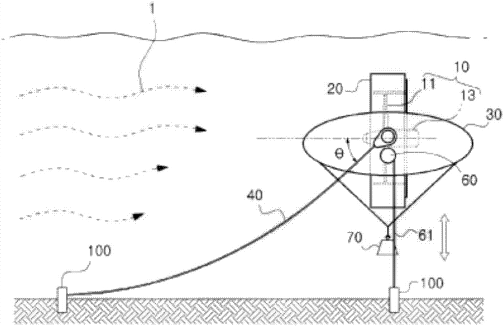
The present invention relates to a submersible power generation platform. A submersible power generation platform according to a first embodiment of the present invention comprises: a generation unit (10) comprising blades (11) and a power generator (13), wherein the blades (11) rotate by being vertically disposed with respect to the flow direction of flowing water and the power generator (13) receives rotation force of the blade (11) to generate electricity; a frame (20) for fixing the generation unit (10) thereinside such that the blades (11) are disposed toward the front portion into which the flowing water flows; a pair of buoyant bodies (30), disposed on both sides of the frame (20), for floating the frame (20) using buoyancy; and at least one fixing rope (40) which fixes and connects the buoyant bodies (30) to a waterway, and has one end connected to a balance center portion (30a) on one face of the buoyant body (30), in which the balance center portion (30a) is determined considering the weight and buoyancy of the generation unit (10), the frame (20), and the buoyant bodies (30), and the flow rate of the flowing water, in order to maintain the balance of the frame (20), wherein the buoyant bodies (30) connected to the fixing rope (40) rise and fall in water such that the blades (11) rotate at a predetermined flow rate varying according to the depth of the water, and are positioned at a predetermined water depth.

Description

technical field [0001] The invention relates to a submersible power generation platform. Background technique [0002] Common power generation methods for generating electric power include thermal power generation using fossil fuels, hydropower generation using falling water, wind power generation using wind, nuclear power generation using nuclear fission, and the like. There are several problems with the described method of generating electricity. In the case of thermal power generation, the combustion of fossil fuels causes pollution, and hydropower generation requires the construction of dams, which destroys the ecosystem and requires huge construction costs. In addition, in the case of wind power generation, windy weather conditions greatly affect the power generation efficiency, so it is difficult to continuously supply power, and nuclear power generation requires considerable costs for preventing radioactive energy leakage and waste disposal. [0003] As means for so...

Claims


Application Information

Patent Timeline
Patent Type & Authority Applications(China)
IPC IPC(8): F03B13/12F03B11/00
CPCF03B11/00F03B13/12B63B1/10B63B21/50B63B2035/4466F05B2240/97F03B13/10F03B17/06Y02E10/30F03B17/061F03B11/06F03B13/22F03B13/264Y02E10/20
Inventor 李东仁
Owner 李东仁
Learn More