Eureka AIR delivers breakthrough ideas for toughest innovation challenges, trusted by R&D personnel around the world.

A waterproof method and waterproof equipment for an ultra-deep diversion tunnel

A water diversion tunnel and ultra-deep technology, applied in tunnels, mining equipment, tunnel lining, etc., to improve quality and efficiency, facilitate advancement, and meet waterproof requirements

Active Publication Date: 2019-08-13
SINOHYDRO ENG BUREAU 4
View PDF3 Cites 0 Cited by
  • Summary
  • Abstract
  • Description
  • Claims
  • Application Information

AI Technical Summary

Problems solved by technology

[0002] The water diversion tunnel is a hydraulic tunnel that diverts water from the water source. It is an important part of the urban underground engineering construction. The ultra-deep water diversion tunnel refers to the water diversion tunnel with a high tunnel depth. The tunnel depth refers to the excavation section of the tunnel. The vertical distance from the top of the diversion tunnel to the natural ground. For such a type of diversion tunnel, the general diversion tunnel waterproofing method can no longer meet the waterproof requirements. The waterproof project at the bottom of the tunnel is easier to implement. The water leakage of the diversion tunnel mainly comes from the top. Affected by many factors, such as the internal and external pressure of the tunnel after the water is passed through, the quality assurance of drinking water, etc., the waterproof of the diversion tunnel is the top priority in the construction process, so the waterproof of the ultra-deep diversion tunnel Technology also urgently needs to be developed

Method used


Image

  • A waterproof method and waterproof equipment for an ultra-deep diversion tunnel
  • A waterproof method and waterproof equipment for an ultra-deep diversion tunnel
  • A waterproof method and waterproof equipment for an ultra-deep diversion tunnel

Examples


Embodiment Construction

[0024] The following will clearly and completely describe the technical solutions in the embodiments of the present invention with reference to the accompanying drawings in the embodiments of the present invention. Obviously, the described embodiments are only some, not all, embodiments of the present invention. Based on the embodiments of the present invention, all other embodiments obtained by persons of ordinary skill in the art without making creative efforts belong to the protection scope of the present invention.

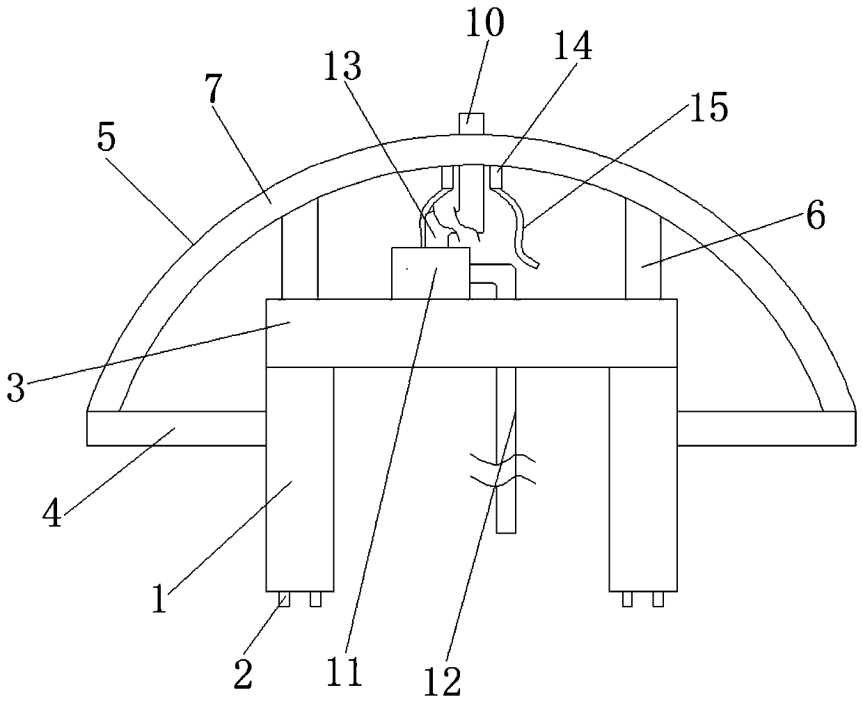
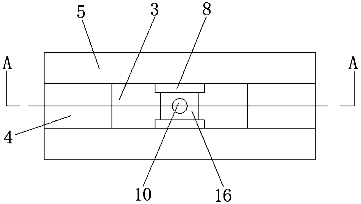
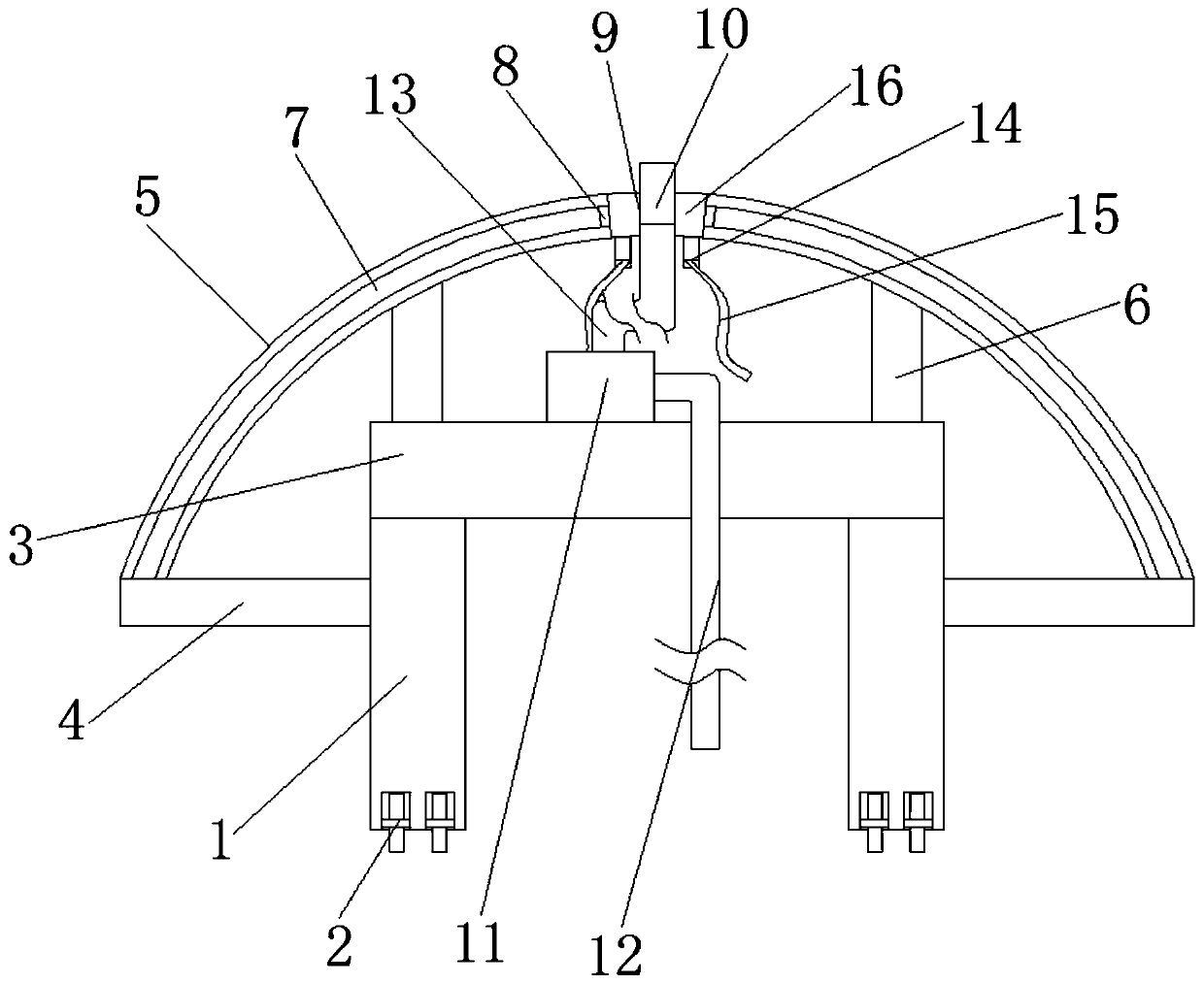
[0025] see Figure 1-3 , the present invention provides a technical solution: a waterproof device for an ultra-deep diversion tunnel, comprising two uprights 1, the bottom ends of the two uprights 1 are fixedly equipped with rollers 2, and the tops of the two uprights 1 are fixedly connected with The lower surface of the horizontal plate 3 and the outer sides of the two columns 1 are fixedly connected to one side of the workbench 4, and two guide rods 5 are ar...


PUM


Abstract

The invention discloses waterproof equipment for ultra-deep buried water guide tunnels. The waterproof equipment comprises two upright columns. Rollers are fixedly mounted at the bottoms of the two upright columns, the lower surface of a transverse plate is fixedly connected with the tops of the two upright columns, a side surface of each worktable is fixedly connected with the outer side surface of the corresponding upright column, two guide rods are arranged above the transverse plate and are symmetric with each other around the central axis of the left side surface of the transverse plate, two ends of the two guide rods are fixedly connected with the ends, which are far away from the corresponding upright columns, of the upper surfaces of the two worktables, and two support rods are fixedly connected with the inner side surface of each guide rod. The invention further discloses a waterproof method for the ultra-deep buried water guide tunnels. The waterproof equipment and the waterproof method have the advantages that a mounting block is arranged between two sliders in a fixedly connected manner, a spray nozzle is mounted in a mounting hole in the mounting block, accordingly, concrete can be conveniently sprayed on the tunnels pertinently for the arc-shaped inner walls of the tunnels, promotion of waterproof engineering can be facilitated, and the tunnel concrete spraying quality and efficiency can be improved.

Description

technical field [0001] The invention relates to the technical field of water diversion tunnel waterproofing, in particular to a waterproof method and waterproof equipment for an ultra-deep buried water diversion tunnel. Background technique [0002] The water diversion tunnel is a hydraulic tunnel that diverts water from the water source. It is an important part of the urban underground engineering construction. The ultra-deep water diversion tunnel refers to the water diversion tunnel with a high tunnel depth. The tunnel depth refers to the excavation section of the tunnel. The vertical distance from the top of the diversion tunnel to the natural ground. For such a type of diversion tunnel, the general diversion tunnel waterproofing method can no longer meet the waterproof requirements. The waterproof project at the bottom of the tunnel is easier to implement. The water leakage of the diversion tunnel mainly comes from the top. Affected by many factors, such as the internal...

Claims


Application Information

Patent Timeline
Patent Type & Authority Patents(China)
IPC IPC(8): E21D11/38E02B9/02E02D29/045E02D29/16
CPCE02B9/02E02D29/045E02D29/16Y02E10/20
Inventor 郭兴忠哈伟德景小青李映来樊光虎韩莉杨永军
Owner SINOHYDRO ENG BUREAU 4
Why Eureka
Eureka Blog
Learn More