
Spring-driven space deployable annular antenna device

A loop antenna, spring-driven technology, applied in the field of aerospace equipment and equipment, can solve the problems of inability to carry out space research tasks, reduce the working stability of the mechanism, and the antenna cannot be deployed normally, so as to achieve a simple motion mechanism and control system, and reduce the overall weight. , the effect of simple assembly

Active Publication Date: 2017-11-24
XIDIAN UNIV
View PDF7 Cites 5 Cited by
  • Summary
  • Abstract
  • Description
  • Claims
  • Application Information

AI Technical Summary

Problems solved by technology

[0003] At present, most spatially deployable antennas use motors as the power source to drive ropes to pull the mechanism to achieve the overall deployment. Although the motor drive has a significant effect on the speed control and impact vibration during the deployment process, the complex drive mechanism not only makes the mechanism The weight has increased, which also reduces the working stability of the mechanism, which not only puts higher requirements on the carrying capacity, but also easily causes the antenna to fail to deploy normally, resulting in the inability to carry out space research tasks, resulting in huge economic losses.

Method used


Image

  • Spring-driven space deployable annular antenna device
  • Spring-driven space deployable annular antenna device
  • Spring-driven space deployable annular antenna device

Examples


Embodiment Construction

[0036] The invention will be further described in detail below in conjunction with the accompanying drawings and embodiments, but it is not used as a basis for any limitation on the invention.

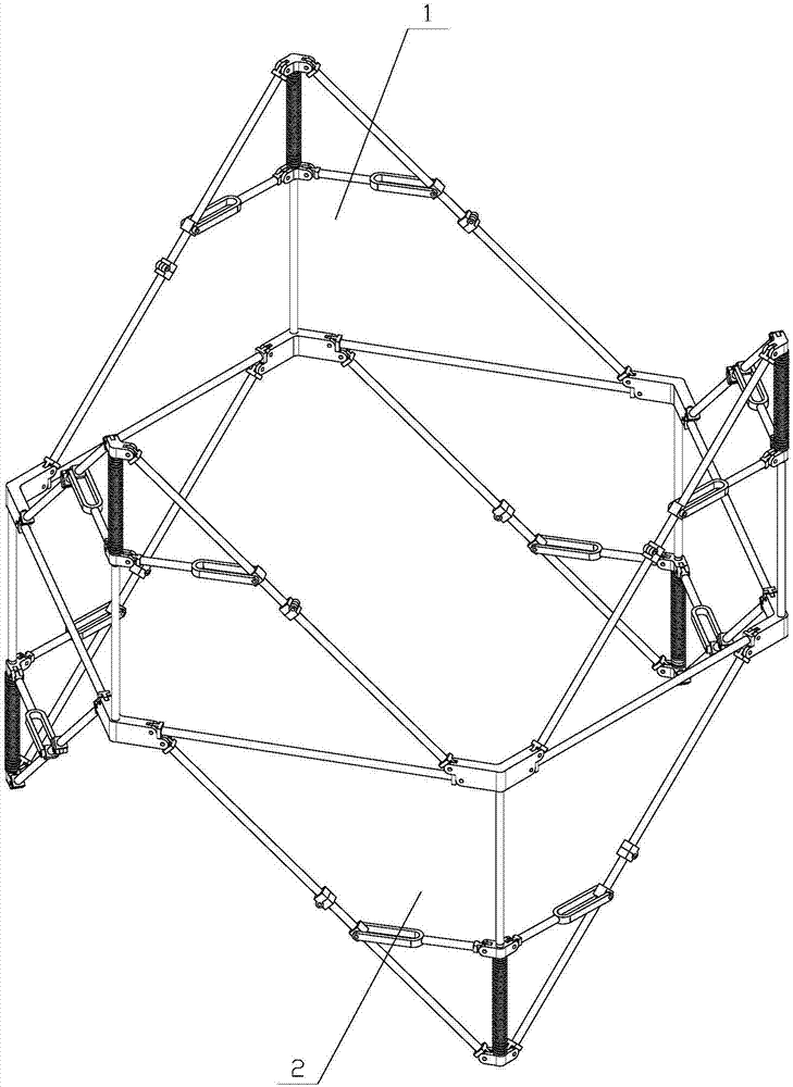
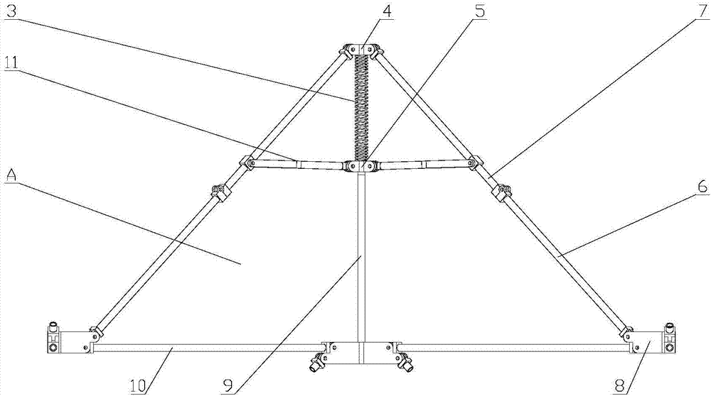
[0037] refer to figure 1 , figure 2 As shown, the spring-driven space expandable loop antenna device generally includes n sets of triangular expandable components 1 and n sets of triangular expandable cooperative components 2 connected below the adjacent n sets of triangular expandable components 1. Equilateral right triangle expandable Unit A, n≥2; n sets of triangular expandable components 1 and n sets of triangular unfolding cooperative components 2 are folded or expanded to form a deployable loop antenna device. Among them, n sets of triangular expandable components 1 are connected end-to-end through four-head hinges 8, n sets of triangular unfolding cooperative components 2 and n sets of triangular expandable components 1 share the same set of cross bars connected by four-head h...


PUM


Abstract

The invention discloses a spring-driven space deployable annular antenna device. The spring-driven space deployable annular antenna device comprises n sets of triangular deployable assemblies and an equilateral right triangle deployable unit A; the equilateral right triangle deployable unit A is composed of n sets of triangular deployable cooperative assemblies connected below the n sets of adjacent triangular deployable assemblies; n is greater than or equal to 2; the n sets of triangular deployable assemblies are connected end to end through four-head hinges; the n sets of triangular deployable cooperative assemblies and the n sets of triangular deployable assemblies share the same set of transverse rods connected through the four-head hinges; the n sets of triangular deployable assemblies and the n sets of triangular deployable cooperative assemblies are connected end to end; and, under the action of the elasticity of a spring, folding or unfolding is carried out, so that the deployable annular antenna device is formed. The device has relatively high geometric stability; a motion mechanism and a control system are simple; after being folded, the device is small in volume and high in accepting rate; an active driving device is unnecessary; the module extensibility is high; accessories are simple; and use requirements of large-aperture space antennas, such as communication satellites and space exploration, can be satisfied.

Description

technical field [0001] The invention relates to a deployable antenna device, in particular to a spring-driven deployable loop antenna device, which belongs to the technical field of aerospace equipment and equipment. Background technique [0002] With the rapid development and deepening of space science and technology, aerospace engineering, and various space exploration activities, the demand for high geometric stability, large scale, and light weight of space structures has become more and more urgent. However, due to the limited carrying space of aerospace vehicles, it is impossible to directly send the formed large-scale space structure into the orbit. Therefore, it is necessary to design a space expandable device with a large folding-to-expand ratio. In the payload compartment of the vehicle; after being launched into orbit, the expandable device is deployed under ground control, and finally locked in the working state. It has become a solution to the above-mentioned pr...

Claims


Application Information

Patent Timeline
IPC IPC(8): H01Q7/02
CPCH01Q7/02
Inventor 孙国辉杜敬利吴晓斌张逸群杨东武蒋翔俊
Owner XIDIAN UNIV
Learn More