
Two-dimensional coding synthetic aperture radar three-dimensional imaging array deformation error compensation method

A technology of synthetic aperture radar and three-dimensional imaging, which is applied in the directions of radio wave reflection/re-radiation, utilization of re-radiation, measurement devices, etc. It can solve the problems of less research on array SAR imaging performance, reduce system accuracy requirements, and remove image The effect of the sidelobe effect

Inactive Publication Date: 2017-11-24
INST OF ELECTRONICS CHINESE ACAD OF SCI
View PDF3 Cites 4 Cited by
  • Summary
  • Abstract
  • Description
  • Claims
  • Application Information

AI Technical Summary

Problems solved by technology

[0003] At present, the related research on array deformation error compensation is mainly about the correction of the direction of arrival estimation error of the receiving beam to the scattering target, and there are few studies on the array SAR imaging performance.

Method used


Image

  • Two-dimensional coding synthetic aperture radar three-dimensional imaging array deformation error compensation method
  • Two-dimensional coding synthetic aperture radar three-dimensional imaging array deformation error compensation method
  • Two-dimensional coding synthetic aperture radar three-dimensional imaging array deformation error compensation method

Examples


Embodiment Construction

[0049] In order to make the purpose, technical solutions and advantages of the present disclosure clearer, the present disclosure will be further described in detail below in conjunction with specific embodiments and with reference to the accompanying drawings.

[0050] It should be noted that, in the drawings or descriptions of the specification, similar or identical parts all use the same figure numbers. Implementations not shown or described in the accompanying drawings are forms known to those of ordinary skill in the art. Additionally, while illustrations of parameters including particular values ​​may be provided herein, it should be understood that the parameters need not be exactly equal to the corresponding values, but rather may approximate the corresponding values ​​within acceptable error margins or design constraints. The directional terms mentioned in the embodiments, such as "upper", "lower", "front", "rear", "left", "right", etc., are only referring to the dire...


PUM


Abstract

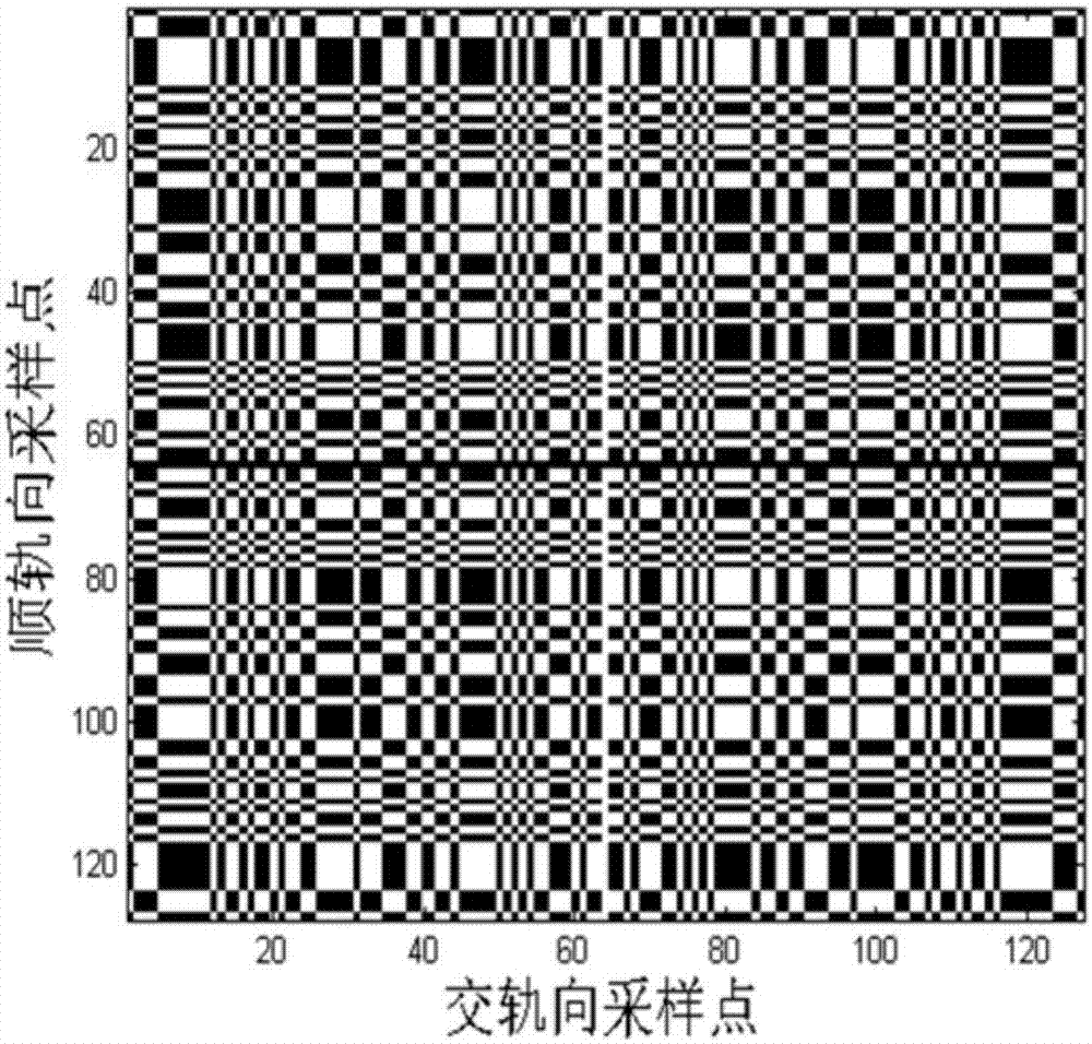
The present invention provides a two-dimensional coding synthetic aperture radar three-dimensional imaging array deformation error compensation method. The method comprises: performing forward rail direction-intersection rail direction space modulation of echo signals through two-dimensional MURA codes; in the condition that an intersection rail direction array has deformation error and performs slow time change along the forward rail direction, performing downward-looking three-dimensional imaging of two paths of echo signals after modulation; performing interference processing of two three-dimensional complex images, and removing a random initial phase and phase errors generated by the deformation errors; establishing an SAR complex image frequency domain coefficient relation after time-domain echo signal-interference; employing a l1 norm optimization criterion, and performing solution of the relation; and performing inverse transformation of the obtained frequency domain coefficients to a spatial domain, and obtaining a target scene three-dimensional image to equivalently realize array deformation error compensation. The three-dimensional imaging array deformation error compensation method obtains a three-dimensional image with good focusing when the precision of the array deformation measurement system is a wavelength magnitude so as to reduce the precision requirement of the array deformation measurement system.

Description

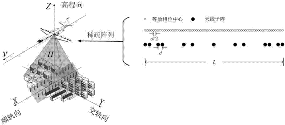
technical field [0001] The present disclosure relates to the field of radar imaging processing, and in particular, to a deformation error compensation method for synthetic aperture radar three-dimensional imaging array based on MURA coding, sparse spectrum and compressed sensing. Background technique [0002] The airborne array SAR obtains high resolution in the range direction by transmitting / receiving broadband signals, obtains high resolution in the azimuth direction by using the relative motion of the antenna platform and the target, and obtains high resolution in the cross-orbit direction by using the array antenna structure arranged in the direction of the cross-orbit of the aircraft. Rate. In the downward-looking working mode, the airborne array SAR can avoid shadow effects and obtain 3D information of complex terrain and urban targets. The sparse array structure can reduce the complexity of the SAR system and the load of the carrier aircraft. According to the princi...

Claims


Application Information

Patent Timeline
Patent Type & Authority Applications(China)
IPC IPC(8): G01S7/41G01S13/90
CPCG01S7/41G01S13/904G01S13/9004
Inventor 李道京田鹤
Owner INST OF ELECTRONICS CHINESE ACAD OF SCI
Learn More