
Stress peak detection method through laser shock peening hole wall

A laser shock strengthening, stress peak technology, applied in force/torque/work measuring instruments, measuring devices, instruments, etc., can solve the problems of unpredictable strengthening effect of small hole components, difficult process control, cumbersome and other problems, to achieve online Monitoring and real-time control, solving measurement difficulties, and detecting the effect of high efficiency

Active Publication Date: 2017-11-24
东台城东科技创业园管理有限公司
View PDF9 Cites 6 Cited by
  • Summary
  • Abstract
  • Description
  • Claims
  • Application Information

AI Technical Summary

Problems solved by technology

[0007] Although the above online detection methods have effectively solved the problem of characterization of the effect of laser shock strengthening, the strengthening effect of small-hole components cannot be predicted; research has shown that the strengthening effect of small-hole components is closely related to the residual stress distribution of the hole wall, but the small-hole Stress measurements on hole walls are difficult, or impossible to detect
[0008] At present, the method of measuring the residual stress distribution of laser shock strengthening mainly relies on the detection of X-ray residual stress tester. This detection method cannot detect the residual stress distribution in the direction of the hole wall. It is difficult to control the process, which limits the development and application of laser shock peening to a certain extent.

Method used


Image

  • Stress peak detection method through laser shock peening hole wall
  • Stress peak detection method through laser shock peening hole wall
  • Stress peak detection method through laser shock peening hole wall

Examples


specific Embodiment

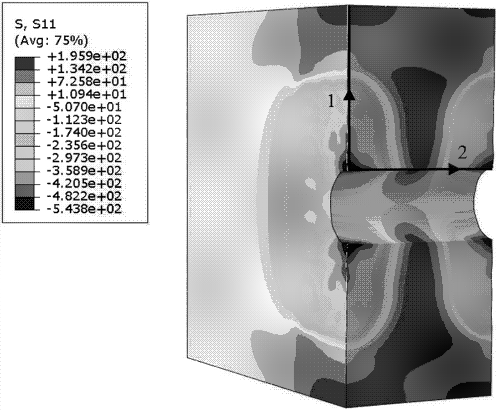
[0057] S01: Establish the finite element model of the laser shock strengthening hole; specifically, define the geometric model of the sample, select the unit, divide the mesh, set the laser shock action area, select the material constitutive model and parameters, and impose boundary constraints;

[0058] In the simulation software ABAQUS, the Y-axis is used as the thickness direction of the model, and the X-Z plane is the laser shock plane to create a geometric model of a rectangular small block. The type of grid division is the explicit linear reduced integration unit C3D8R, and the grid division process In order to carry out mesh refinement in the area of ​​2 times the length of the spot radius on the three coordinate axes; the mesh division process is to carry out mesh refinement in the area of ​​2 times the length of the spot radius on the three coordinate axes; the material constitutive model uses Johnson -Cook model; said imposing boundary conditions is imposing symmetry ...


PUM

PropertyMeasurementUnit
Pulse widthaaaaaaaaaa
Diameteraaaaaaaaaa
Power densityaaaaaaaaaa

Abstract

The invention provides a stress peak detection method through a laser shock peening hole wall. The stress peak detection method comprises the following steps that a finite element model of the laser shock peening hole is established; simulation calculation is performed; a laser loading curve is determined according to the laser shock process parameters; a shock trajectory path is set; a simulation calculation module is started; hole opening finite element simulation is started; laser shock peening simulation is performed on the acting area of laser shock, and then hole opening simulation is performed on the shock center area; the laser shock process parameters are changed and the steps are repeated; a relation curve between the residual stress and the hole wall stress peak of the hole wall surface theory is drawn; the sample is prepared, and laser shock peening processing and hole opening are performed on the sample; the surface residual stress of the hole of the sample is measured for statistical analysis; and the actual residual stress peak of the hole wall is estimated. The surface residual stress near the hole angle can be measured according to the relation curve between the laser shock peening surface residual stress near the hole angle and the hole wall stress peak.

Description

technical field [0001] The invention relates to the field of physical and chemical analysis of material strengthening treatment, in particular to a stress peak detection method for strengthening hole walls with laser shock. Background technique [0002] It is of great significance to adjust the laser shock parameters to achieve the best impact effect on the material according to the material properties and the laser shock intensity effect. However, the strengthening effect of small-hole components is different from the strengthening of ordinary surfaces. The strengthening effect of the material surface cannot be determined; or the strengthening of the material impact surface does not necessarily lead to the strengthening of small-hole components, or it may be because of this Therefore, to study the stress distribution of the hole wall of the small hole component, it is necessary to strengthen the hole wall while impact strengthening the impact surface; but it is difficult to...

Claims


Application Information

Patent Timeline
IPC IPC(8): G01L5/00
CPCG01L5/0047
Inventor 姜银方季彬姜文帆甘学东虞文军朱恒李旭黄建云
Owner 东台城东科技创业园管理有限公司
Learn More