
Electric control hydraulic actuating mechanism of direct-drive clutch of motor and method for controlling electric control hydraulic actuating mechanism

An electronically controlled hydraulic and actuator technology, which is applied in the field of automobile transmission, can solve problems such as application restrictions of low-end and low-end automobiles, hidden dangers of reliability and safety, and production difficulties, and achieve the effects of energy saving, environmental protection, stable integration, and rapid separation

Pending Publication Date: 2017-11-24
JILIN UNIV
View PDF11 Cites 4 Cited by
  • Summary
  • Abstract
  • Description
  • Claims
  • Application Information

AI Technical Summary

Problems solved by technology

[0003] Chinese patent applications "hydraulic automatic clutch device" (patent application number 201510372510.6) and "an electronically controlled automatic clutch for automobiles" (patent application number 201410553564.8) install related valve bodies in the mechanism, the structure is relatively complex, production is difficult, and the cost is high , there is a certain security risk in its reliability
At the same time, due to the application of high-speed solenoid valves and oil circuit panels, the application of integrated hydraulic clutches in low-end and mid-end vehicles is limited

Method used


Image

  • Electric control hydraulic actuating mechanism of direct-drive clutch of motor and method for controlling electric control hydraulic actuating mechanism
  • Electric control hydraulic actuating mechanism of direct-drive clutch of motor and method for controlling electric control hydraulic actuating mechanism

Examples


specific Embodiment approach

[0033] In order to further illustrate the technical solution of the present invention, in conjunction with the accompanying drawings, the specific implementation of the present invention is as follows:

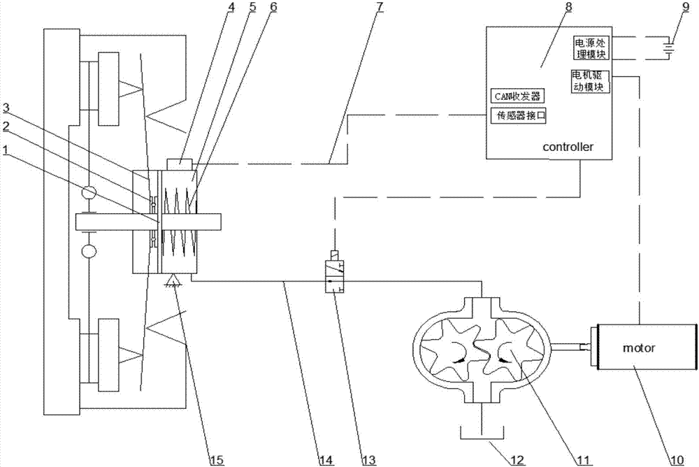
[0034] Such as figure 1 As shown, the present invention provides a motor direct drive type clutch electro-hydraulic actuator, and the actuator is composed of a mechanical assembly and an electric control assembly.

[0035] The mechanical assembly includes a clutch release bearing 2 , a hydraulic cylinder 5 , a return spring 6 , a DC motor 10 , a gear pump 11 , an oil reservoir 12 , a switching valve 13 , a hydraulic oil pipe 14 and a support 15 .

[0036] The DC motor 10 is fixed on the support 15 by fastening bolts; the gear pump 11 is also fixed on the support by fastening bolts, and the gear pump 11 is a medium-low pressure small displacement gear pump.

[0037] The output shaft of the DC motor 10 is coaxially connected with the input shaft of the gear pump 11 through a sp...


PUM


Abstract

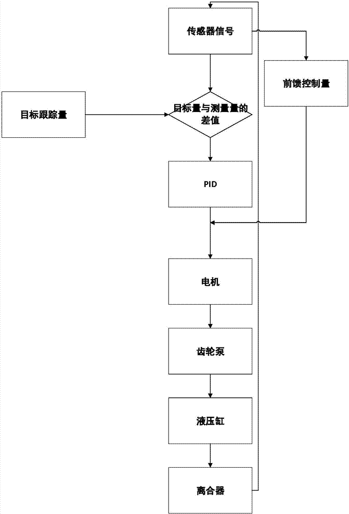
The invention provides an electric control hydraulic actuating mechanism of a direct-drive clutch of a motor and a method for controlling the electric control hydraulic actuating mechanism. The electric control hydraulic actuating mechanism comprises a mechanical assembly and an electric control assembly. A clutch release bearing of the mechanical assembly is mounted on a piston rod on the left side of a hydraulic cylinder, a return spring is mounted on a piston rod on the right side of the hydraulic cylinder, two ends of the clutch release bearing closely cling to release fingers of a clutch diaphragm spring and an end surfaces of a hydraulic cylinder piston, and the direct-current motor, gear pumps and a switch valve are sequentially connected with a cavity on the right side of the hydraulic cylinder; a controller of the electric control assembly is in signal connection with the switch valve and the direct-current motor, and motor control programs are burned in the controller. The method includes allowing the controller to transmit control signals to the direct-current motor by the aid of the motor control programs according to current vehicle operating signals; controlling the gear pumps to control displacement of the hydraulic cylinder piston in the hydraulic cylinder; ultimately controlling the clutch. The electric control hydraulic actuating mechanism and the method have the advantages that the electric control hydraulic actuating mechanism is simple in structure and good in reliability, and the clutch can be stably, quickly and accurately controlled.

Description

technical field [0001] The invention belongs to the technical field of automobile transmission, and in particular relates to a motor direct-drive clutch electric control hydraulic actuator and a control method thereof. Background technique [0002] During the running of the car, the driver frequently depresses the clutch pedal to start and stop the vehicle and shift gears, which will cause driver fatigue. Installing an automatic clutch actuator is an effective way to solve this problem. It is mainly divided into electronically controlled electric, electronically controlled hydraulic and electronically controlled pneumatic. Among them, the hydraulic actuator is widely used for its advantages of large energy capacity and high control precision. in the car clutch. [0003] Chinese patent applications "hydraulic automatic clutch device" (patent application number 201510372510.6) and "an electronically controlled automatic clutch for automobiles" (patent application number 20141...

Claims


Application Information

Patent Timeline
IPC IPC(8): F16D25/12
CPCF16D25/14
Inventor 高炳钊李鑫张超陈虹
Owner JILIN UNIV
Learn More