Independent presser foot control mechanism of embroidery machine

A technology of a control mechanism and an embroidery machine, which is applied in the field of embroidery machines, and can solve the problems of difficult individual adjustment of the initial stroke of the presser foot, poor applicability of different fabrics, and large impact of the fabric, so as to improve the quality of embroidery, improve adaptability, and improve work efficiency. Effect

Active Publication Date: 2017-11-24
ZHUJI MAYA ELECTRIC APPLIANCE MACHINERY
View PDF7 Cites 7 Cited by
  • Summary
  • Abstract
  • Description
  • Claims
  • Application Information

AI Technical Summary

Problems solved by technology

[0004] The above-mentioned solution has improved some problems of the prior art to a certain extent, but the solution still has at least the following defects: the initial stroke of the presser foot is difficult to be adjusted independently, the applicability to different fabrics is poor, the impact of the presser foot on the fabric is strong, Loud working noise and low working efficiency

Method used


Image

  • Independent presser foot control mechanism of embroidery machine
  • Independent presser foot control mechanism of embroidery machine
  • Independent presser foot control mechanism of embroidery machine

Examples


Embodiment Construction

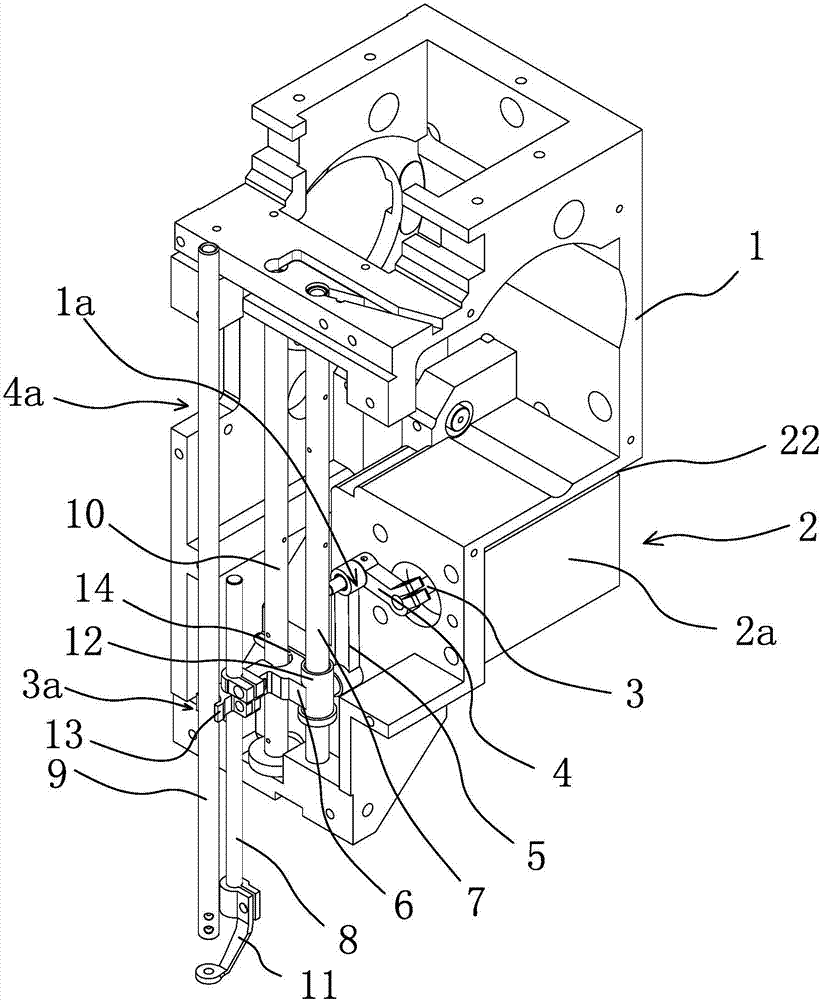
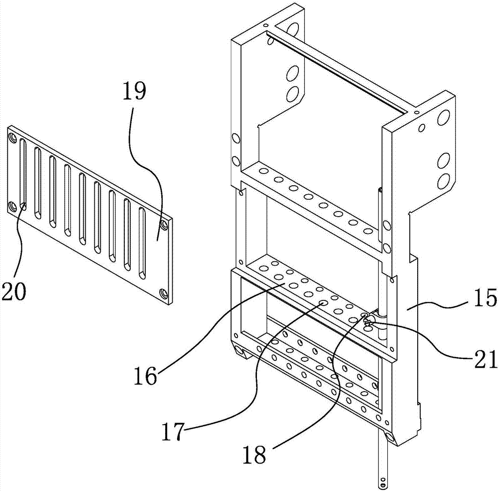
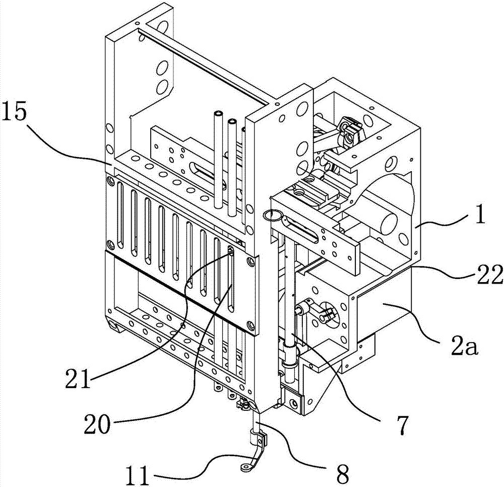
[0022] Such as Figure 1-3 As shown, the independent presser foot control mechanism of this embroidery machine includes a headstock 1, and a drive mechanism 2 is arranged on the headstock 1. The drive mechanism 2 is connected with a presser foot drive seat 6 through a connecting rod transmission structure 1a, and the presser foot is driven The seat 6 is movably sleeved on the presser foot driving rod 7 which is fixedly connected to the headstock 1, and one end of the presser foot driving seat 6 is connected with a presser foot driving seat 6 which can move up and down along the axial direction of the presser foot driving rod 7 to follow the pressure. The presser foot needle bar 8 that moves synchronously with the foot driving seat 6 is connected with the presser foot 11, and the circumferential outer side of the presser foot driving seat 6 is also connected with the presser foot driving seat 6 through the rod body positioning structure 3a. The needle bar assembly 4a is movable...


PUM


Abstract

The invention provides an independent presser foot control mechanism of an embroidery machine, aiming at solving the existing technical problem. The independent presser foot control mechanism comprises a machine head seat, wherein a driving mechanism is arranged on the machine head seat and connected with a presser foot driving seat through a connecting rod transmission structure; the presser foot driving seat movably sleeves a presser foot driving rod which is fixedly connected with the machine head seat; one end of the presser foot driving seat is connected with a presser foot needle bar which can synchronously move along the presser foot driving seat when the presser foot driving seat moves up and down along the axial direction of the presser foot driving rod; a presser foot is connected onto the presser foot needle bar; and a needle bar assembly which is movably arranged relative to the presser foot driving seat and does not interfere the presser foot driving seat when the presser foot driving seat moves up and down is connected to the peripheral outer side of the presser foot driving seat through a rod body positioning structure. The independent presser foot control mechanism disclosed by the invention has the advantages of adjustable initial height of the presser foot, low spindle load and the like.

Description

technical field [0001] The invention belongs to the technical field of embroidery machines, and relates to an independent presser foot control mechanism of the embroidery machine. Background technique [0002] When the existing embroidery machine is in use, the driving wheel drives the needle bar to run up and down, and the presser foot runs along with the needle bar and the presser foot through the connecting rod arranged on the needle bar or the needle bar driving wheel or directly driven by the needle bar. The presser feet in the machine head are directly installed on the needle bar of the needle bar frame of the machine head seat, and a retaining ring is set on the needle bar. The retaining ring is pressed on the presser foot by a spring. Due to the existence of the spring, the cloth is not affected during work. The impact force on the surface is relatively large, which affects the quality of the finished product, and the pressure of the presser foot depends on the press...

Claims


Application Information

Patent Timeline
Patent Type & Authority Applications(China)
IPC IPC(8): D05C9/20
CPCD05C9/20Y02P90/02
Inventor 张丁元魏大江俞永刚
Owner ZHUJI MAYA ELECTRIC APPLIANCE MACHINERY
Why Eureka
Try Eureka