
Needle bar frame body of high-speed embroidery machine

A needle bar frame and embroidery machine technology, applied in the field of needle bar frame bodies, can solve the problems of poor operation stability of the presser foot, position deviation, and high failure rate, and achieve improved functional integration, high combination stability, and structural combination. high degree of effect

Pending Publication Date: 2021-03-16
ZHEJIANG YUELONG SEWING EQUIP
View PDF2 Cites 0 Cited by
  • Summary
  • Abstract
  • Description
  • Claims
  • Application Information

AI Technical Summary

Problems solved by technology

[0005] Of these two existing technologies, the former is relatively complex in terms of structure and power composition, has a relatively high failure rate during operation, and occupies a large installation space of the needle bar frame, which is not conducive to the setting of other components and is prone to mechanical interference. The problem of the latter is that the presser foot has poor running stability and is prone to position deviation, which is not conducive to maintaining the high-efficiency and stable state of the needle bar frame.

Method used


Image

  • Needle bar frame body of high-speed embroidery machine
  • Needle bar frame body of high-speed embroidery machine
  • Needle bar frame body of high-speed embroidery machine

Examples


Embodiment Construction

[0038] The present invention will be described in further detail below according to the accompanying drawings and examples of implementation.

[0039] The directional terms such as up, down, left, right, front, back, front, back, top, and bottom that are mentioned or may be mentioned in this specification are defined relative to the structures shown in the drawings. The words " "Inside" and "outside" respectively refer to the direction toward or away from the geometric center of a specific component. They are relative concepts, so they may change accordingly according to their different positions and different usage states. Accordingly, these or other directional terms should not be construed as limiting terms.

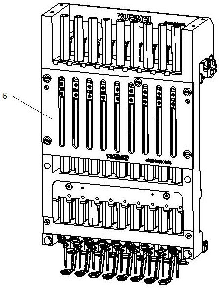
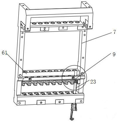
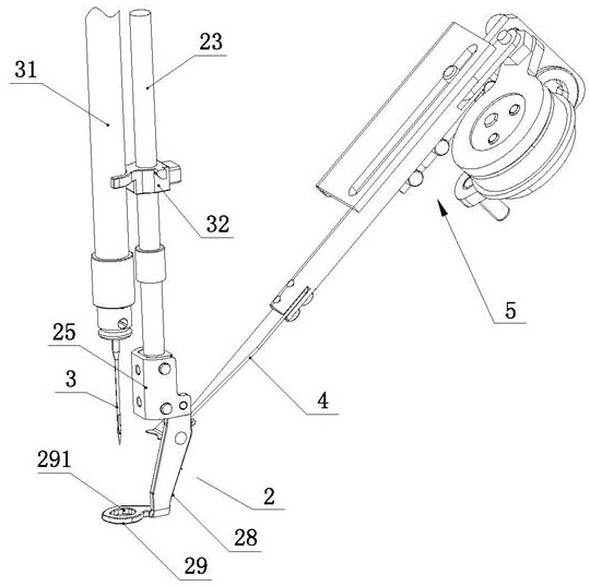
[0040] refer to Figure 1-Figure 14 According to the present invention, the needle bar frame body of the high-speed embroidery machine includes a needle bar frame 6, a needle bar 31 mounted on the needle bar frame 6 and a presser foot 2 matched therewith, the embroid...


PUM


Abstract

The invention discloses a needle bar frame body of a high-speed embroidery machine. The needle bar frame body comprises a needle bar frame, a needle bar installed on the needle bar frame and a presserfoot matched with the needle bar, wherein the presser foot comprises a presser foot rod and a presser foot structure connected to the bottom end of the presser foot rod, the presser foot structure isprovided with a first thread clamping structure and a second thread clamping structure, a hook knife penetrates through the space between the first thread clamping structure and the second thread clamping structure, the first thread clamping structure can move relative to the second thread clamping structure and can reset, the first thread clamping structure makes contact with the second thread clamping structure when being located at a reset position, the presser foot rod is provided with a matching structure, the needle rod frame is provided with a locking structure used for preventing thematching structure from moving forwards, the needle rod frame is provided with an unlocking mechanism capable of enabling the locking structure and the matching structure to generate relative displacement so as to relieve the blocking effect of the locking structure on the matching structure. The needle bar frame body has the beneficial effects that the higher function integration degree is achieved, and the technical purpose of stably keeping upper thread clamping is achieved.

Description

technical field [0001] The invention relates to a needle bar frame body of a high-speed embroidery machine, which is applied in the technical field of embroidery machines. Background technique [0002] The presser foot on the embroidery machine is the part that completes the cloth pressing action during the embroidery process of the embroidery machine, and the thread hooking plate on the embroidery machine is a part that cooperates with the thread trimming device, that is, when the thread needs to be trimmed, the embroidery machine stops working, and the thread hooking plate Under the action of the corresponding driving mechanism, it moves back and forth, so as to pick up the upper thread on the fabric that needs to be cut, and then realize the thread trimming operation under the action of the thread trimming device. [0003] Prior art CN201620415947.3 discloses an upper thread clamping device and an embroidery machine head. The disclosed upper thread clamping device include...

Claims


Application Information

Patent Timeline
IPC IPC(8): D05C11/08D05C9/20
CPCD05C9/20D05C11/08
Inventor 陈天池张汉苗郑邓飞楼凯
Owner ZHEJIANG YUELONG SEWING EQUIP
Learn More