Thread hooking device for preventing deformation of pull rod and embroidery machine

A thread catcher and pull rod technology, which is applied in the field of thread catcher, can solve the problems of torsion spring failure, ball detachment, etc., and achieve the effects of stable thread hooking action, increased rotational resistance, and reduced maintenance costs

Active Publication Date: 2021-07-30
ZHEJIANG XINSHENG SEWING EQUIP
View PDF7 Cites 0 Cited by
  • Summary
  • Abstract
  • Description
  • Claims
  • Application Information

AI Technical Summary

Problems solved by technology

[0004] Since the two ends of the chute pass through the two opposite side walls on the slider, and the slider can rotate relative to the hooking rod, there is a risk of the ball falling out of the chute
[0005] In addition, the thread hooking fork used in the existing thread hooker is usually composed of two V-shaped structures, which are divided into a ball installation section for installing balls and a swing section connected with the hook knife, a ball installation section and a swing section. There is a torsion spring in between, so when the hook knife is locked, although the pull rod still drives the ball installation section to move, it will not drive the hook knife to move, but in the actual use process, the torsion spring is prone to failure, resulting in the frequent need to replace the hook.

Method used


Image

  • Thread hooking device for preventing deformation of pull rod and embroidery machine
  • Thread hooking device for preventing deformation of pull rod and embroidery machine
  • Thread hooking device for preventing deformation of pull rod and embroidery machine

Examples


Embodiment 1

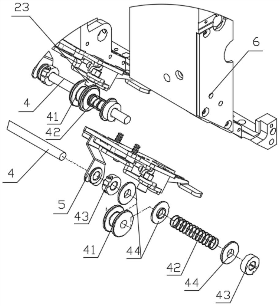
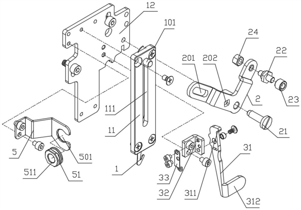
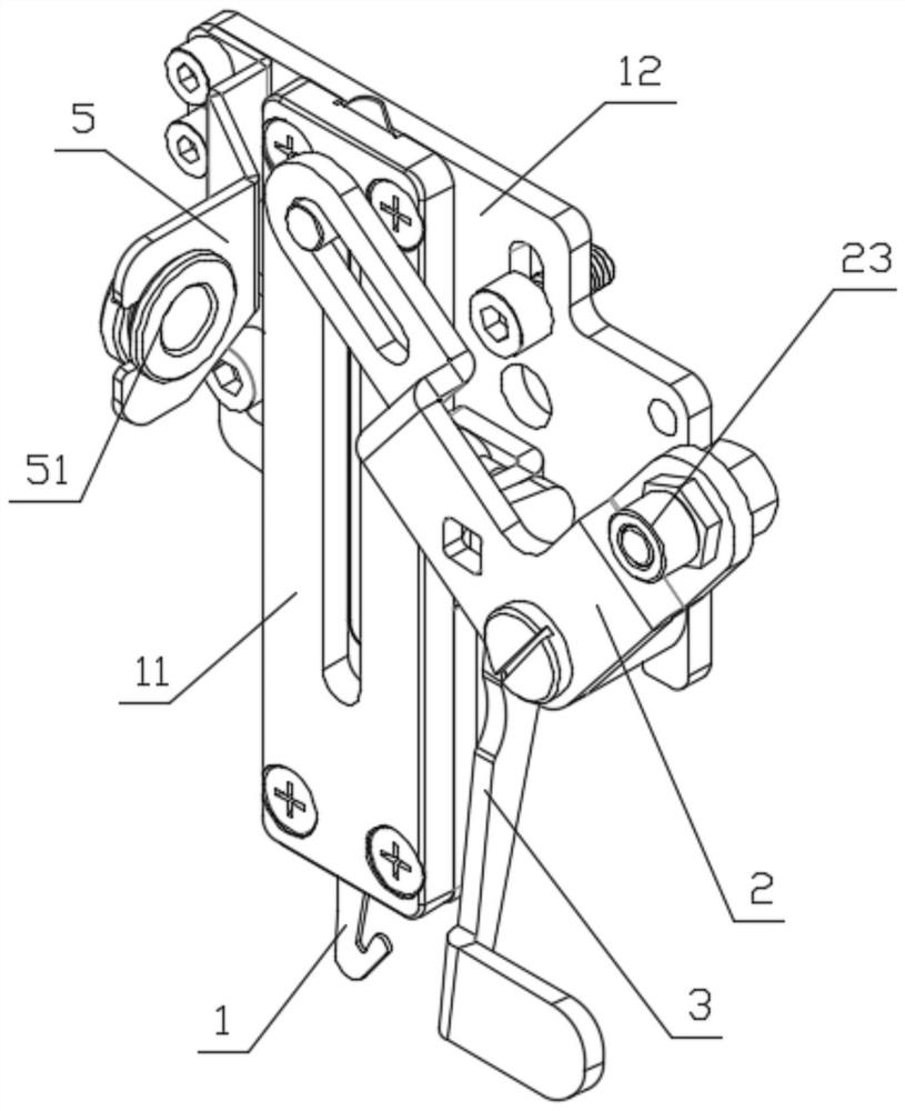
[0032] Such as Figure 1 to Figure 3 As shown, the hooking device includes a hooking driver, a hooking rod 4, a hooking fork 2 and a hooking knife 1. The hooking driver drives the hooking rod 4 to reciprocate in a straight line, and the hooking rod 4 is rotatably connected with a ball guide Block 41, the ball guide block 41 is provided with a ball guide groove arranged in a ring around the wire hooking rod 4, the wire hooking shift fork 2 is provided with a ball 23, and the ball guide block 41 is driven by the wire hooking rod 4 to move linearly to and fro , the ball 23 rolls in the ball guide groove to make the line-hooking shift fork 2 swing back and forth, and the line-hooking shift fork 2 drives the hook knife 1 to linearly reciprocate to realize the line-hooking. After the ball 23 rolls in the ball guide groove, no matter how the ball guide block rotates with respect to the thread-drawing pull bar, the ball is still in the ball guide groove and will not disengage.

[003...

Embodiment 2

[0046] An embroidery machine, comprising the thread catcher in the above embodiment, such as figure 1 As shown, the thread catcher is installed on the embroidery machine head housing 6 .


PUM


Abstract

The invention discloses a thread hooking device for preventing deformation of a pull rod and an embroidery machine. The thread hooking device comprises a thread hooking driver, the thread hooking pull rod, a thread hooking shifting fork and a hooking knife; the thread hooking driver drives the thread hooking pull rod to do linear reciprocating motion; the thread hooking pull rod is rotationally connected with a ball guide block; the ball guide block is provided with a ball guide groove annularly formed around the thread hooking pull rod; the thread hooking shifting fork is provided with a ball; the ball guide block is driven by the thread hooking pull rod to do linear reciprocating motion; the ball rolls in the ball guide groove to enable the thread hooking shifting fork to do reciprocating swing motion; the thread hooking shifting fork drives the hooking knife to do linear reciprocating motion to achieve thread hooking; the thread hooking pull rod is movably nested with a compression spring on the side of the ball guide block; and the thread hooking pull rod is fixedly provided with two limiting ferrules correspondingly on the two sides of a combination body of the ball guide block and the pressure spring. Even if the ball guide block rotates relative to the thread hooking pull rod, the ball is still in the ball guide groove and cannot be separated; and the compression spring is adopted to replace a torsional spring, and the compression spring is long in service life and relatively low in cost, so that the maintenance cost can be reduced.

Description

technical field [0001] The invention relates to the technical field of embroidery machines, in particular to a thread catcher. Background technique [0002] The existing thread hooker is connected to the thread hooking pull rod, and is fixed by screws. When the thread hooker is in use, the pull bar will be deformed, resulting in unstable thread hooking and affecting the quality of embroidery. [0003] In order to solve the technical problem of the deformation of the tie rod, the applicant applied for a wire catcher on February 11, 2018. A slider is provided on the wire hook pull rod, and the slider is provided with a chute perpendicular to the axial direction of the wire hook pull rod. The slide block reciprocates in a straight line with the thread hooking pull rod, and the thread hooking fork is provided with a ball, which rolls in the chute to make the thread hooking fork reciprocate and swing, and the thread hooking fork drives the hook knife to move linearly to and fro t...

Claims


Application Information

Patent Timeline
IPC IPC(8): D05C11/00
CPCD05C11/00
Inventor 王海江田桂郁楼府相
Owner ZHEJIANG XINSHENG SEWING EQUIP
Why Eureka
Try Eureka