Separating device

A separation device and spraying device technology, applied in the direction of filtration and separation, separation methods, chemical instruments and methods, etc., can solve the problems of difficult cleaning, blockage of filter equipment, and low efficiency of separation process, so as to improve separation efficiency and separation quality , avoid blocking, good effect of continuous operation

Pending Publication Date: 2017-11-24
四川祥龙生物工程技术有限公司
View PDF10 Cites 2 Cited by
  • Summary
  • Abstract
  • Description
  • Claims
  • Application Information

AI Technical Summary

Problems solved by technology

However, when separating complex components such as solids (or crystals), highly viscous precipitates, liquids, etc., the traditional separation equipment cannot achieve the separation effect, or the separation is separated by a combination of multiple equipment, resulting in the separation process low efficiency
[0004] Taking one of the processes of traditional Chinese medicine as an example, the concentrated liquid from the traditional Chinese medicine concentration tank needs to be filtered again. Under certain medicinal materials or compatibility, the concentrated liquid from the concentration tank will precipitate into viscous asphalt during the standing and cooling process. At the same time, solid (or crystalline) substances will be precipitated on the surface of the concentrated liquid and the position of the container wall, which will cause great difficulties for subsequent filtration, especially the presence of viscous asphalt-like precipitates, which will easily lead to blockage of filter equipment. At the same time The filter channel of traditional separation equipment is difficult to separate from the containing space of the concentrate, which makes it easy to block the filter channel during the standstill and cooling of the concentrate
The existing scheme has low continuity in the operation process, and it is difficult to clean up after a single filtration, which makes the filtration efficiency very low and the labor intensity is high

Method used


Image

  • Separating device
  • Separating device

Examples


Embodiment Construction

[0026] All features disclosed in this specification, or steps in all methods or processes disclosed, may be combined in any manner, except for mutually exclusive features and / or steps.

[0027] Any feature disclosed in this specification, unless specifically stated, can be replaced by other alternative features that are equivalent or have similar purposes. That is, unless expressly stated otherwise, each feature is one example only of a series of equivalent or similar features.

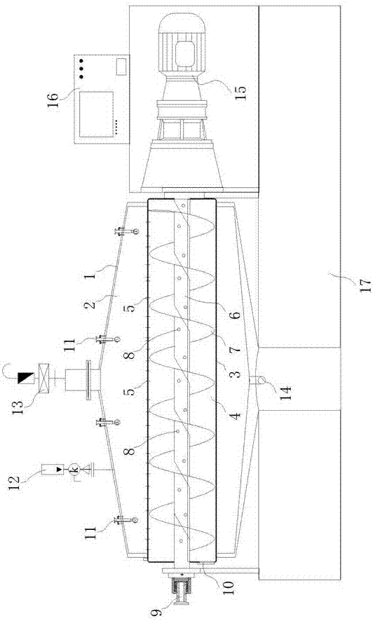
[0028] Separating device of the present invention, its structure is as figure 1 shown. The unit includes:

[0029] A first casing 1 made of stainless steel is used to form a first cavity 2 .

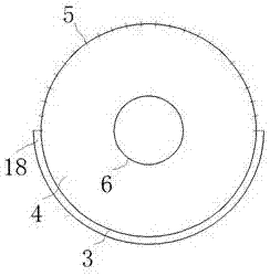
[0030] A second casing 3 made of stainless steel is used to form a second cavity 4 .

[0031] Wherein, the second casing 3 is arranged horizontally, and the horizontal direction referred to in the present invention refers to horizontality, or a slight, certain degree of inclination in the horizontal directio...


PUM


Abstract

The invention discloses a separating device and belongs to the technical field of process equipment. The device comprises a first shell and a second shell which is transversely distributed, wherein a part of or all the second shell is wrapped by the first shell, a filtering channel used for filtering is arranged at a part wrapped by the first shell of the second shell, a cavity of the first shell and a cavity of the second shell are communicated through the filtering channel, and the second shell is arranged in a rotatable mode to change the position height of the filtering channel to enable materials to be filtered by the filtering channel into the first shell. The device achieves material separation by utilizing a rotating mode. When being applied to a traditional Chinese medicine preparing process, the device can solve the problem that the filtering channel is plugged by concentrated solution thick precipitation; meanwhile, the filtering channel is not in contact with a concentrated solution in standing and cooling processes, so that the filtering channel is prevented from being plugged by solid (or crystal) matters generated in the standing and cooling processes; thus, separating efficiency and separating quality are greatly improved; the device also can be applied to separating processes of other materials.

Description

technical field [0001] The invention relates to a separation device, in particular to a device for complex component separation, and belongs to the technical field of process equipment. Background technique [0002] Separation is an important link in the process, and the separation device is also an important equipment in the process equipment. [0003] Ordinary separation process, high-efficiency separation can be achieved by filter press, filter screen or other types of equipment. However, when separating complex components such as solids (or crystals), highly viscous precipitates, liquids, etc., the traditional separation equipment cannot achieve the separation effect, or the separation is separated by a combination of multiple equipment, resulting in the separation process low efficiency. [0004] Taking one of the processes of traditional Chinese medicine as an example, the concentrated liquid from the traditional Chinese medicine concentration tank needs to be filter...

Claims


Application Information

Patent Timeline
Patent Type & Authority Applications(China)
IPC IPC(8): B01D36/04
CPCB01D36/04
Inventor 叶学彬钟光俊
Owner 四川祥龙生物工程技术有限公司
Why Eureka
Try Eureka