Manual roller bracket for air bags

A technology of air bags and rollers, applied to workbenches, manufacturing tools, etc., can solve the problems of complex use, high energy consumption, and expensive self-adjusting roller brackets, and achieve the effect of simple structure, convenient use, and meeting needs

Inactive Publication Date: 2014-02-26
ANHUI SHENGYUN ENVIRONMENTAL ENG
View PDF5 Cites 0 Cited by
  • Summary
  • Abstract
  • Description
  • Claims
  • Application Information

AI Technical Summary

Problems solved by technology

In actual production and use, due to the high cost, high energy consumption and complicated use of self-adjusting roller brackets, enterprises cannot provide more self-adjusting roller brackets for production

Method used


Image

  • Manual roller bracket for air bags
  • Manual roller bracket for air bags

Examples


Embodiment Construction

[0013] The present invention will be described in further detail below in conjunction with the accompanying drawings and specific embodiments.

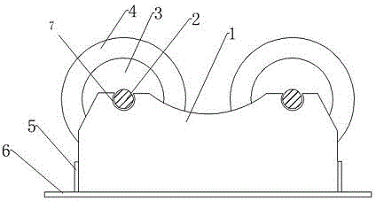
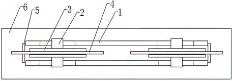
[0014] Such as figure 1 and figure 2 As shown, a manual air bag roller bracket includes a stand plate 1, a main shaft 2, an auxiliary wheel 3, a main wheel 4, a reinforcing rib 5 and a bottom plate 6, and the two stand plates 1 are relatively parallel and arranged on the bottom plate 6 , two grooves 7 are provided at the top of the stand board 1, the grooves 7 of the two stand boards 1 are arranged oppositely, and the two ends of the two spindles 2 are respectively arranged at the grooves 7 of the two stand boards 1 , the central position of the main shaft 2 is provided with a main wheel 4 . The two auxiliary wheels 3 are located on both sides of the main wheel 4 , and the auxiliary wheels 3 are arranged on the main shaft 2 . The reinforcing rib 5 is located in the middle of the two ends of the two standing plates 1 , and the bott...


PUM


Abstract

The invention discloses a manual roller bracket for air bags. The manual roller bracket comprises stand plates, spindles, auxiliary wheels, main wheels, reinforcing ribs and a bottom plate. The two stand plates are oppositely and parallelly arranged on the bottom plate, two grooves are formed in the top of each stand plate, the grooves of the two stand plates are opposite to one another, two ends of each spindle are respectively arranged in the corresponding grooves of the two stand plates, and the main wheels are arranged in the middles of the spindles. The manual roller bracket has the advantages that operation is carried out by the aid of the main wheels arranged on the stand plates, accordingly, the manual roller bracket is convenient to use and simple in structure, and requirements of air bag manufacturing procedures can be met.

Description

[0001] technical field [0002] The invention relates to an air bag roller bracket, in particular to a manual air bag roller bracket. Background technique [0003] The self-adjusting roller bracket consists of two sets of main and auxiliary machines, namely the active roller frame and the passive roller frame. Each group of the self-adjusting series of active and passive frames has four rollers. The rollers are made of an inner iron core and an outer rubber structure. . The operation of the active roller frame is synchronously driven by the speed-regulating motor through two worm gear reducers, and the speed-regulating controller is used to realize stepless speed change. The mechanical transmission noise is low, the workpiece rotation is stable, and the workpiece rotation speed is 5-70m / h. Each group of clamp frames can be automatically adjusted when the diameter of the workpiece reaches a certain range. When the diameter is the smallest, the lower wheels of each group of c...

Claims


Application Information

Patent Timeline
Patent Type & Authority Applications(China)
IPC IPC(8): B25H1/00
Inventor 程萍
Owner ANHUI SHENGYUN ENVIRONMENTAL ENG
Why Eureka
Try Eureka