Multipoint high-temperature sample gas collecting system capable of working reliably
A technology for collecting system and sample gas, applied in the field of high-temperature flue gas multi-point sampling devices in thermal power plants, can solve the problems of inability to provide uninterrupted operation, intermittent data collection, inability to achieve high-temperature extraction, etc., to avoid smoke and dust clogging, Improved work reliability, improved stability and reliability
- Summary
- Abstract
- Description
- Claims
- Application Information
AI Technical Summary
Problems solved by technology
Method used
Image


Examples
Embodiment approach
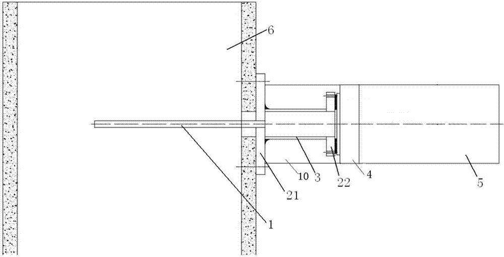
[0058] A.1 Front sampling probe rod
[0059] The front-end sampling probe is mainly composed of a sampling probe, a pre-embedded DN65 flange assembly (large flange, a large flange cover), and a conversion joint between the probe and the probe. The main implementation method is to weld the DN65 pre-embedded flange to the flue in advance, and the welding angle needs to be at an angle of 89° with the flue wall, and prepare the connection between the probe rod and the outer threaded joint of the ferrule. Such as Figure 14 shown.
[0060] A.2 filter box
[0061] The filter box 10 is mainly composed of a sampling gas path, a backflushing gas path, a heating circuit and its control part (temperature controller 34), which is used to connect the front-end sampling probe rod and the heating pipeline, and its main function is to filter the flue gas in the flue Dust, to prevent the back-end pipeline from clogging; the collected sample gas is heated at a constant temperature of 150°C t...
specific Embodiment approach
[0067] 1. Place the control cabinet on the measuring point platform, and connect the installed probe rod with the sampling gas path of the filter box, the blowback gas path and the control cabinet through the heating pipeline;
[0068] 2. Pass the compressed air source into the buffer tank on the right, and open the metering valve at the front end of the vacuum generator to adjust the intake air volume;
[0069] 3. Connect the main power supply to the main switch in the control cabinet, and turn on each sub-control circuit breaker;
[0070] 4. Debug the temperature control instrument on the control panel of layer A of the control cabinet, and adjust the temperature of each heating pipeline to be between 120-160°C;
[0071] 5. Adjust the flow of each air intake path to ensure that the flow of each path is basically balanced;
[0072] 6. After heating and pumping for 15 minutes to 1 hour, connect the air outlet on the right side of the cabinet to the analyzer and observe the da...
PUM
| Property | Measurement | Unit |
|---|---|---|
| length | aaaaa | aaaaa |
| thickness | aaaaa | aaaaa |
| thickness | aaaaa | aaaaa |
Abstract
Description
Claims
Application Information
 - R&D
- Intellectual Property
- Life Sciences
- Materials
- Tech Scout
- Unparalleled Data Quality
- Higher Quality Content
- 60% Fewer Hallucinations
Browse by: Latest US Patents, China's latest patents, Technical Efficacy Thesaurus, Application Domain, Technology Topic, Popular Technical Reports.
© 2025 PatSnap. All rights reserved.Legal|Privacy policy|Modern Slavery Act Transparency Statement|Sitemap|About US| Contact US: help@patsnap.com