A Coal-fired Boiler Pollutant Emission Reduction Optimization Collaborative Flue Gas Waste Heat Depth Utilization System

A technology for flue gas waste heat and coal-fired boilers, which is applied in the fields of combustion product treatment, preheating, and emission prevention. Reliability and economy, reducing the temperature gradient of wind and smoke, reducing the effect of heat transfer exergy loss

Active Publication Date: 2019-03-26
ELECTRIC POWER RESEARCH INSTITUTE OF STATE GRID SHANDONG ELECTRIC POWER COMPANY +1
View PDF4 Cites 0 Cited by
  • Summary
  • Abstract
  • Description
  • Claims
  • Application Information

AI Technical Summary

Problems solved by technology

However, through field application, it is found that these devices generally have the problem that the inlet flue gas temperature deviates from the optimal value, which directly affects the reliability and economy of equipment operation, mainly reflected in the following aspects: (1) The inlet flue gas temperature of the SCR flue gas denitrification system is low , which is more prominent under low load, resulting in a decrease in denitrification efficiency, and in severe cases, it may even fail to be put into operation; (2) The flue gas temperature at the inlet of the electrostatic precipitator is too high, resulting in a corresponding decrease in dust removal efficiency; (3) The flue at the inlet of the desulfurization tower is biased High, resulting in increased desulfurization water consumption
However, in the traditional coal-fired boiler air-smoke system, these devices lack the means of flue temperature adjustment, and cannot effectively control the inlet flue temperature, thus restricting the energy-saving and emission-reduction capabilities of coal-fired units
In view of the above problems, scholars at home and abroad have carried out many special studies on the waste heat utilization system of coal-fired boilers and the pollutant emission reduction system, and have achieved great results. There is a large correlation. If the two are not turned on during the operation adjustment process, there will be follow-up, and the operation performance of different equipment cannot be taken into account, thus limiting the mining of the unit's energy-saving and emission-reduction capabilities.

Method used


Image

  • A Coal-fired Boiler Pollutant Emission Reduction Optimization Collaborative Flue Gas Waste Heat Depth Utilization System

Examples


Embodiment Construction

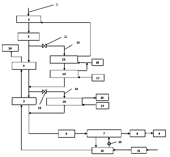
[0015] Attached below figure 1 The present invention will be further described.

[0016] A coal-fired boiler pollutant emission reduction optimization cooperative flue gas waste heat deep utilization system, including the main flue 1 and the chimney 9 of the boiler 24, the flue gas in the main flue 1 passes through the first-stage high-pressure economizer 2, SCR flue gas successively Gas denitrification system 3, high-temperature air preheater 4, low-temperature air preheater 5, electrostatic precipitator 6, primary low-temperature smoke-water heat exchanger 7, desulfurization tower 8 and chimney 9. It also includes: a high-temperature bypass flue 10, whose inlet end is connected to the main flue 1 between the SCR flue gas denitrification system 3 and the high-temperature air preheater 4, and whose outlet end is connected to the high-temperature air preheater 4 and the low-temperature In the main flue 1 between the air preheaters 5, in the high-temperature bypass flue 10, a s...


PUM


Abstract

The invention relates to a coal-fired boiler pollutant emission reduction co-optimization flue gas waste heat deep utilization system. Heat transfer loss in the system can be reduced. The flue gas waste heat utilization rate is increased. The flue gas temperature of an inlet of pollutant emission reduction equipment can be regulated and controlled. The capability of energy conservation and emission reduction of a unit is improved as well. The system comprises a boiler main flue, a high-temperature bypass flue and a low-temperature bypass flue, wherein a first-stage high-pressure economizer, an SCR flue gas denitration system, a high-temperature air preheater, a low-temperature air preheater, an electric dust collector, a first-stage low-temperature flue gas and water heat exchanger, a desulfurization tower and a chimney are sequentially in the boiler main flue in the flow direction of flue gas; a second-stage high-pressure economizer and a high-temperature flue gas and water heat exchanger are sequentially arranged in the high-temperature bypass flue in the flow direction of the flue gas; a second-stage low-temperature flue gas and water heat exchanger is arranged in the low-temperature bypass flue; the first-stage high-pressure economizer and the second-stage high-pressure economizer are arranged in series; an air-water heat exchanger at an outlet of an air blower and the first-stage low-temperature flue gas and water heat exchanger realize closed water circulating heat exchange through a circulating water pump.

Description

technical field [0001] The invention relates to the field of coal-fired power generation, in particular to a coal-fired boiler pollutant emission reduction optimization cooperative flue gas waste heat depth utilization system. Background technique [0002] Coal is the main primary energy in my country, accounting for more than 60% of the total energy consumption, of which coal consumption for power generation accounts for about 50%. For coal-fired boilers, exhaust heat loss is the main factor affecting the thermal efficiency of the boiler, which accounts for more than 50% of the boiler heat loss. If the exhaust gas temperature is estimated at 130-160°C, the waste heat of the flue gas at the tail of the boiler can be recovered every year. Save about 70 million tons of standard coal; in addition, the emissions of pollutants such as NOx, SO2 and dust generated by coal-fired boilers account for about 39%, 31% and 14% of the total national emissions. Emission reduction has alway...

Claims


Application Information

Patent Timeline
Patent Type & Authority Patents(China)
IPC IPC(8): F22D1/36F23J15/02
CPCF22D1/36F23J15/02F23J2215/10F23J2215/20F23J2217/102
Inventor 周新刚刘福国侯凡军赵显桥姜波王守恩
Owner ELECTRIC POWER RESEARCH INSTITUTE OF STATE GRID SHANDONG ELECTRIC POWER COMPANY
Why Eureka
Try Eureka