Data transmission system, method and device
A technology of a data transmission system and a data transmission method, applied in the application field of communication technology, can solve the problems of low video transmission efficiency, inability to effectively transmit video data with anti-interference, and achieve the effect of improving video transmission efficiency
- Summary
- Abstract
- Description
- Claims
- Application Information
AI Technical Summary
Problems solved by technology
Method used
Image
Examples
Embodiment 1
[0033] According to an embodiment of the present invention, an embodiment of a data transmission system is provided, figure 1 is a schematic structural diagram of a data transmission system according to an embodiment of the present invention, such as figure 1 As shown, the data transmission system includes:
[0034] The sending terminal 12 and the receiving terminal 14; wherein, the sending terminal 12 sends the data source through at least two communication interfaces; the receiving terminal 14 is connected with the sending terminal 12 for receiving the data source sent by the sending terminal 12 through at least two communication interfaces , wherein at least two communication interfaces in the sending terminal 12 are correspondingly connected to at least two communication interfaces in the receiving terminal 14 .
[0035] Specifically, the data transmission system provided by the embodiment of this application can be applied to the field of data transmission. In this appli...
Embodiment 2
[0050] According to an embodiment of the present invention, an embodiment of a data transmission method is provided. It should be noted that the steps shown in the flowcharts of the accompanying drawings can be executed in a computer system such as a set of computer-executable instructions, and, although in The flowcharts show a logical order, but in some cases the steps shown or described may be performed in an order different from that shown or described herein.
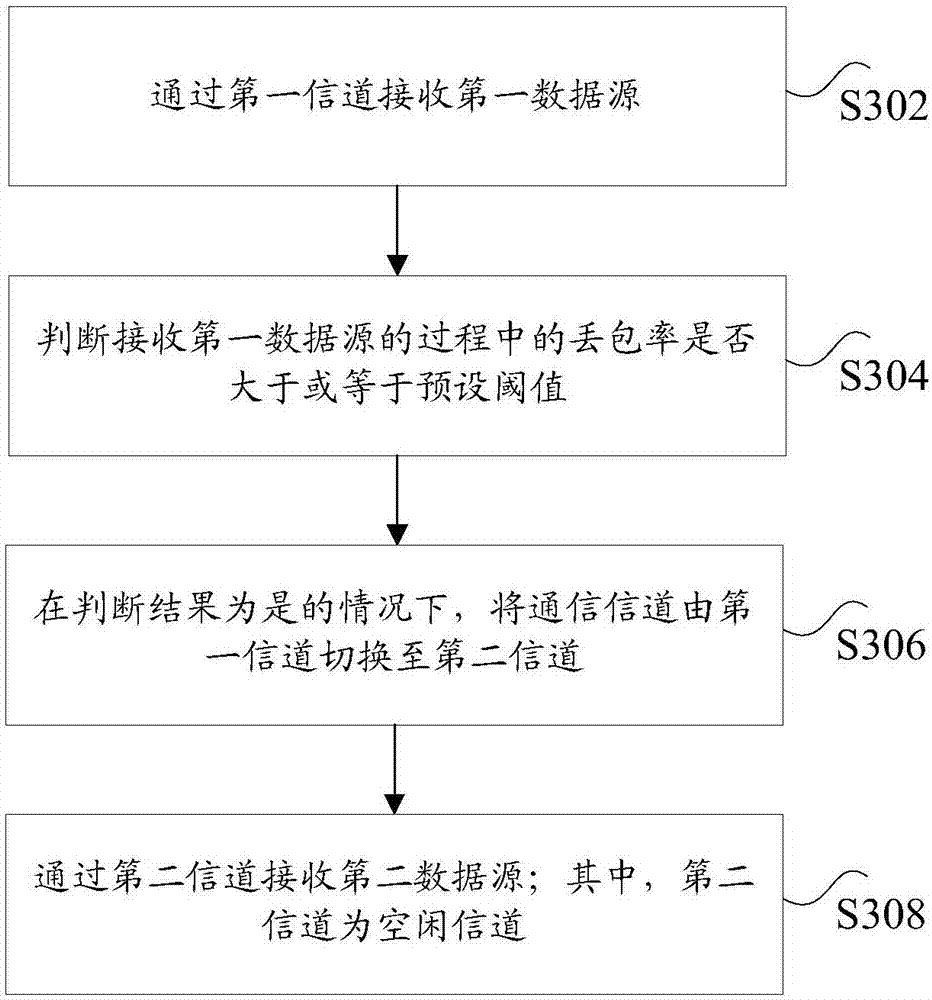
[0051] image 3 is a schematic flowchart of a data transmission method according to an embodiment of the present invention, such as image 3 As shown, on the receiving terminal side, the method includes the following steps:
[0052] Step S302, receiving a first data source through a first channel;
[0053] Step S304, judging whether the packet loss rate in the process of receiving the first data source is greater than or equal to a preset threshold;
[0054] Step S306, if the judgment result is yes, switch the c...
Embodiment 3
[0077] Figure 5 is a schematic structural diagram of a data transmission device according to an embodiment of the present invention, such as Figure 5 As shown, on the receiving terminal side, the data transmission device includes:
[0078] The first receiving module 52 is used to receive the first data source through the first channel; the statistics module 54 is used to judge whether the packet loss rate in the process of receiving the first data source is greater than or equal to the preset threshold; the switching module 56 uses If the judgment result is yes, the communication channel is switched from the first channel to the second channel; the second receiving module 58 is configured to receive the second data source through the second channel; wherein, the second channel is an idle channel.
[0079] In the embodiment of the present invention, the first data source is received through the first channel; it is judged whether the packet loss rate in the process of receiv...
PUM
 Abstract
Description
Claims
Application Information
 - R&D
- Intellectual Property
- Life Sciences
- Materials
- Tech Scout
- Unparalleled Data Quality
- Higher Quality Content
- 60% Fewer Hallucinations
Browse by: Latest US Patents, China's latest patents, Technical Efficacy Thesaurus, Application Domain, Technology Topic, Popular Technical Reports.
© 2025 PatSnap. All rights reserved.Legal|Privacy policy|Modern Slavery Act Transparency Statement|Sitemap|About US| Contact US: help@patsnap.com


