
Water extractor for printing and dyeing

A dehydrator and water tank technology, which can be used in liquid/gas/vapor removal with squeeze rollers, liquid/gas/vapor removal by air jet method, and equipment configuration for processing textile materials, etc., can solve problems such as poor practicability and achieve convenient The effect of preliminary filtration and centralized purification

Inactive Publication Date: 2017-11-17
姚飞
View PDF0 Cites 6 Cited by
  • Summary
  • Abstract
  • Description
  • Claims
  • Application Information

AI Technical Summary

Problems solved by technology

[0004] The purpose of the present invention is to provide a dehydrator for printing and dyeing, which has the advantage of strong practicability and solves the problem of poor practicability of traditional printing and dyeing dehydrators

Method used

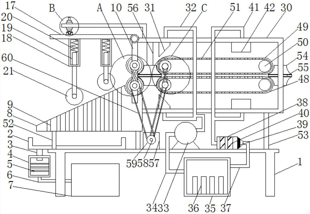
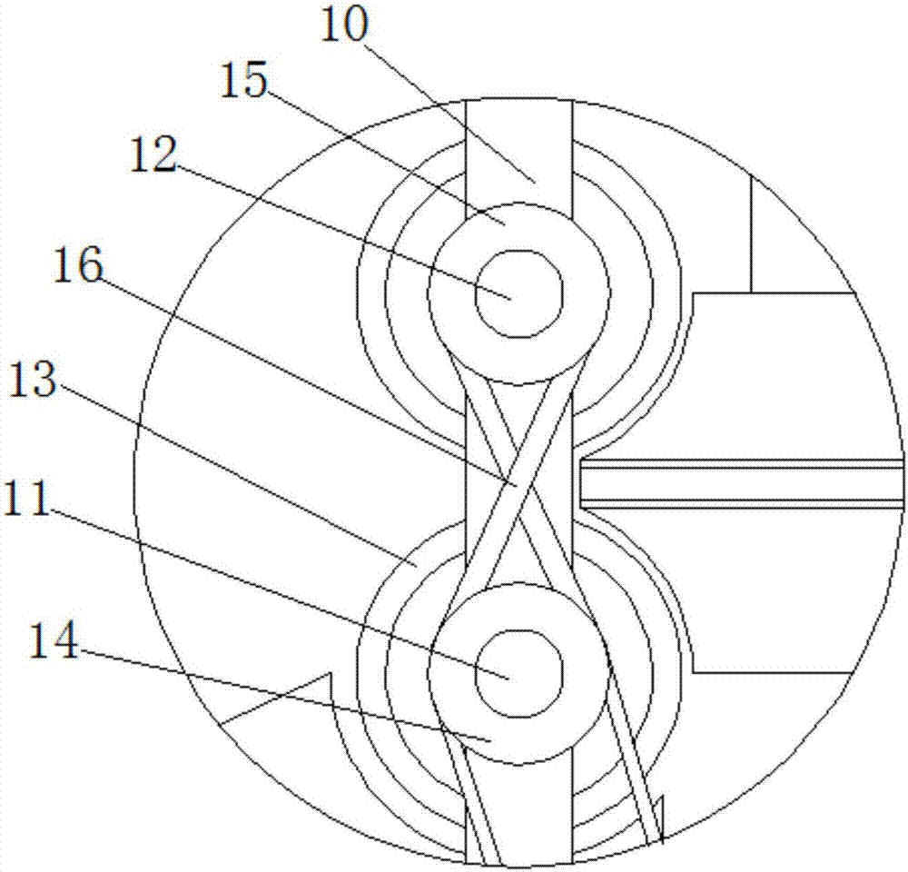

Image

  • Water extractor for printing and dyeing
  • Water extractor for printing and dyeing
  • Water extractor for printing and dyeing

Examples


Embodiment Construction

[0025] The following will clearly and completely describe the technical solutions in the embodiments of the present invention with reference to the accompanying drawings in the embodiments of the present invention. Obviously, the described embodiments are only some, not all, embodiments of the present invention. Based on the embodiments of the present invention, all other embodiments obtained by persons of ordinary skill in the art without making creative efforts belong to the protection scope of the present invention.

[0026] see Figure 1-4, the present invention provides a technical solution: a dehydrator for printing and dyeing, comprising an underframe 1, a motor 57 is connected to the middle of the top of the underframe 1, and the front of the motor 57 is socketed with an organic wheel 59 through a crankshaft 58. The outer side is movably connected with the outside of the first rotating shaft 11 and the third rotating shaft 43 with a belt 60, the left side of the top of...


PUM


Abstract

The invention discloses a water extractor for printing and dyeing. A ponding groove is connected to the left side of the top of an underframe, a filter chamber is connected to the outer side of a water discharging pipe in a sleeving mode, and a trapezoid body is arranged on the top of the ponding groove; water discharging grooves are formed in the trapezoid body at equal intervals, telescopic pillars are connected to the inner cavities of hollow pillars in a penetrating mode, and a roller is movably connected between two telescopic pillars; the top of a track ball penetrates through a baffle, a threaded rod is connected to the top of the track ball, and a threaded sleeve is connected to the outer side of the threaded rod in a sleeving mode; air injection plates are connected to two sides of the inner cavity of a drying chamber, a dehumidification chamber is communicated with one end of an air returning pipe, and a first conveying belt and a second conveying belt are movably connected to the outer sides of a third rotation shaft and a fourth rotation shaft respectively. According to the water extractor for printing and dyeing, the trapezoid body, the roller, the telescopic pillars, the first conveying belt, the second conveying belt, the air injection plates, the water discharging grooves, the filter chamber, the threaded rod, the threaded sleeve and a bent plate are used, and the function of high practicability of the water extractor for printing and dyeing is achieved.

Description

technical field [0001] The invention relates to the technical field of printing and dyeing equipment, in particular to a dehydrator for printing and dyeing. Background technique [0002] As we all know, in the printing and dyeing process, in the post-processing of the cloth after printing and dyeing, the cloth needs to be washed and dehydrated, and the dehydration of the cloth generally uses a special dehydrator. [0003] The traditional dehydration machine for printing and dyeing is generally a drum structure, which mainly uses the centrifugal force when the dehydration bucket rotates at high speed to throw the water on the fabric out of the dehydration bucket, and this dehydration method is easy to cause wrinkles and damage to the fabric. After the traditional printing and dyeing dehydrator removes the water from the fabric, it is generally discharged directly into the sewage tank without the extraction of impurities, which increases the difficulty of later purification. D...

Claims


Application Information

Patent Timeline
Patent Type & Authority Applications(China)
IPC IPC(8): D06B15/02D06B15/09D06B23/20
CPCD06B15/02D06B15/09D06B23/20
Inventor 姚飞
Owner 姚飞
Learn More