
Pneumatic high-temperature superconducting magnetic levitation rail vehicle system

A high-temperature superconducting, rail car technology, applied in electric vehicles, vehicle components, railway vehicle testing, etc., can solve the problems of increasing train operating costs, expensive guide rail manufacturing costs, and reducing train effective load capacity, so as to improve the effective load capacity. , the structure is simple, the effect of reducing the production cost

Inactive Publication Date: 2017-11-17
TIANJIN UNIV +1
View PDF5 Cites 0 Cited by
  • Summary
  • Abstract
  • Description
  • Claims
  • Application Information

AI Technical Summary

Problems solved by technology

Since the "long fixed piece" power system uses a linear motor wound on the guide rail as the driving part of the high-speed magnetic levitation column, the cost of making the guide rail is extremely expensive; the "short fixed piece" power system uses a linear induction motor wound on the passive track ( LIM) as a driving component, because the LIM is too heavy, the effective load capacity of the train is reduced. Although this system saves the production cost of the guide rail, it increases the operating cost of the train.

Method used


Image

  • Pneumatic high-temperature superconducting magnetic levitation rail vehicle system
  • Pneumatic high-temperature superconducting magnetic levitation rail vehicle system
  • Pneumatic high-temperature superconducting magnetic levitation rail vehicle system

Examples


Embodiment Construction

[0029] Specific embodiments of the present invention will be described below in conjunction with the accompanying drawings, so that those skilled in the art can better understand the present invention.

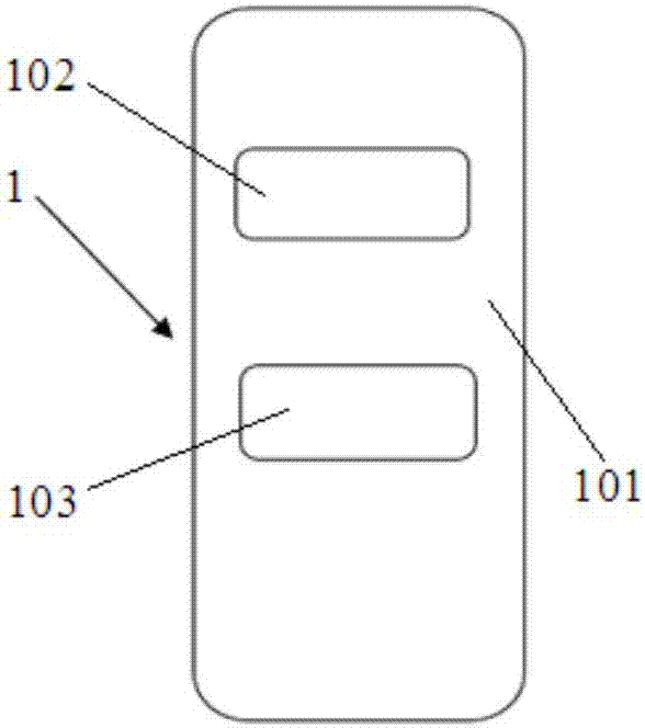
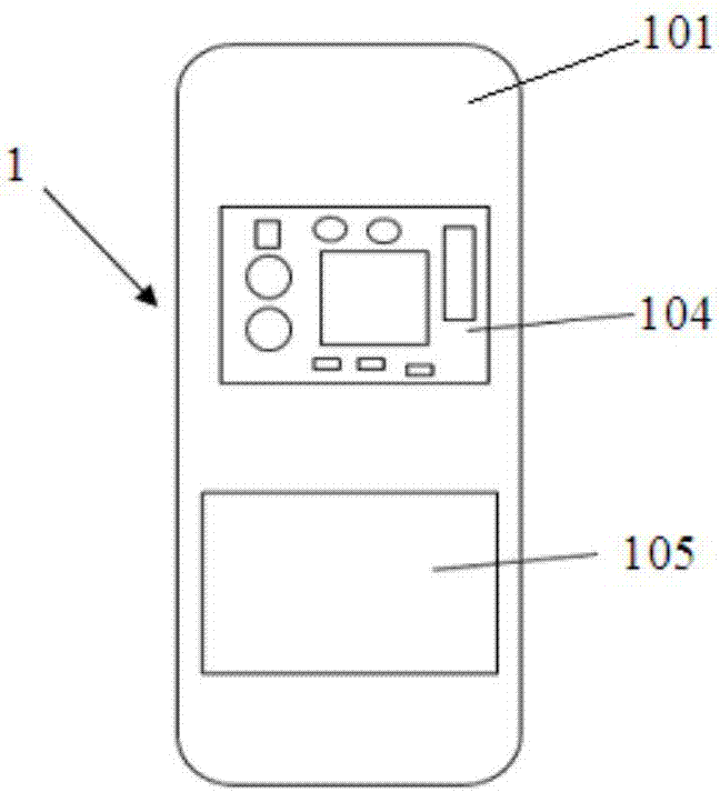
[0030] A pneumatic high-temperature superconducting maglev rail car system of the present invention includes a remote controller 1 , a permanent magnet rail 2 and a superconducting rail car 3 . Such as figure 1 with figure 2 As shown, the remote controller 1 includes a remote control box 101. The remote control box 101 is provided with a button one 102 and a button two 103. The button one 102 represents "forward", and the button two 103 represents "backward". There are remote control battery 104 and signal transmission system 105, remote control battery 104 adopts 9V battery, is used for powering signal transmission system 105, and signal transmission system 105 is used for issuing instructions.

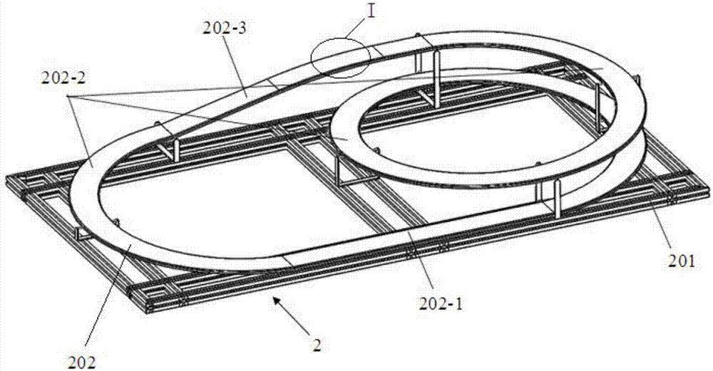
[0031] Such as image 3 with Figure 4 As shown, the permanent magnet track...


PUM


Abstract

The invention discloses a pneumatic high-temperature superconducting magnetic levitation rail vehicle system. The pneumatic high-temperature superconducting magnetic levitation rail vehicle system comprises a remote controller, a permanent magnetic rail and a superconducting rail vehicle. The remote controller comprises a remote control box, a first pressing key, a second pressing key, a remote control battery and a signal emitting system. The permanent magnetic rail is made up of a circular rail fixed on a bracket. The superconducting rail vehicle comprises a vehicle type outer shell, and the front part of the vehicle type outer shell is internally provided with a vehicle body battery and a signal receiving system. The circular rail is evenly inlaid with permanent magnet bulks. The permanent magnet bulks are distributed in rows in the width direction of the circular rail and are distributed in columns in the length direction of the circular rail. An injecting hole is formed in the top of the vehicle type outer shell. A power system which adopts an air driving way is arranged at the tail of the vehicle type outer shell. A low-temperature vessel is arranged at the bottom of the vehicle type outer shell. The low-temperature vessel comprises a vessel room and an upward liquid nitrogen canned channel. High temperature superconducting bulks are evenly and symmetrically arranged in the vessel room. According to the pneumatic high-temperature superconducting magnetic levitation rail vehicle system, the manufacturing cost of the permanent magnetic rail is reduced, and the payload capacity of the superconducting rail vehicle is improved.

Description

technical field [0001] The invention relates to the technical field of superconducting magnetic levitation rail cars, and mainly relates to the driving technology of superconducting magnetic levitation rail cars, and more specifically, relates to a pneumatic high temperature superconducting magnetic levitation rail car system. Background technique [0002] As the world's first manned high-temperature superconducting maglev test vehicle was successfully developed in Southwest Jiaotong University in 2000, which further confirmed the possibility of high-temperature superconductor blocks being used in maglev vehicles, more and more scientific workers began to devote themselves to superconductivity. In-depth research in the field of maglev, and the superconducting maglev railcar running at high speed without mechanical contact is one of the subjects that people are committed to research. The superconducting maglev rail car system consists of two parts: a high-temperature supercon...

Claims


Application Information

Patent Timeline
Patent Type & Authority Applications(China)
IPC IPC(8): B60L13/04G01M17/08
CPCB60L13/04G01M17/08
Inventor 信赢田波杨天慧李继春夏芳敏魏子镪
Owner TIANJIN UNIV
Learn More