Waste-gas treating system

A waste gas treatment and pretreatment technology, applied in the direction of gas treatment, membrane technology, dispersed particle separation, etc., can solve the problems of short service life, poor treatment effect, waste of water source, etc., achieve uniform mixing, better treatment effect, and use long life effect

Pending Publication Date: 2017-11-14
南京凯创金源科技开发有限公司
View PDF0 Cites 1 Cited by
  • Summary
  • Abstract
  • Description
  • Claims
  • Application Information

AI Technical Summary

Problems solved by technology

[0003] (1) Activated carbon adsorption, its service life is short, and it needs to be replaced once a week in the case of serious pollution, and the replacement operation is complicated, which greatly increases the operating cost;
[0004] (2) The water curtain structure is used to mix the exhaust gas. During the treatment, the exhaust gas is in front of the water curtain, and the induced draft fan is behind the water curtain. When working, there must be enough water in the tank to form a water curtain, wasting water, and the treatment effect is not good. ;
[0005] (3) The spray tower is combined with photo-oxygen catalytic equipment, and the spray tower is used to make the mixing between the spray liquid and the waste gas uneven, the waste gas treatment effect is not good, and the energy consumption is high

Method used


Image

  • Waste-gas treating system
  • Waste-gas treating system
  • Waste-gas treating system

Examples


Embodiment Construction

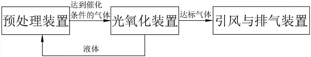
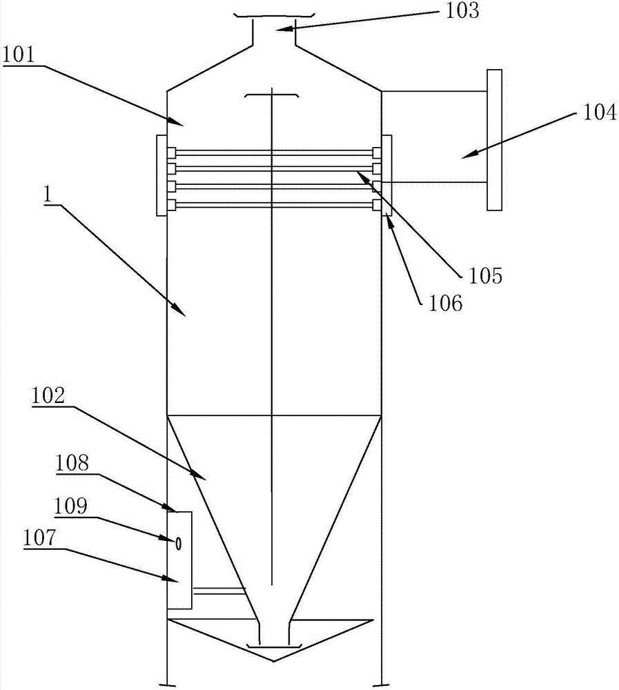
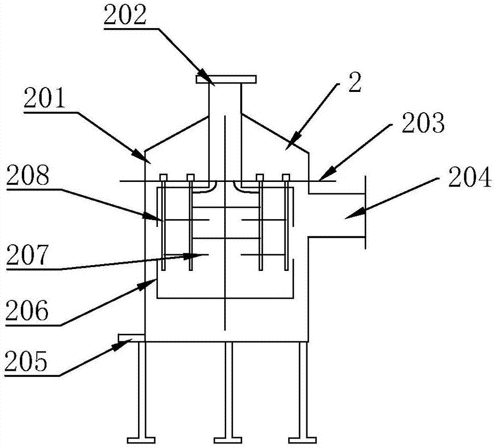
[0032] Such as figure 1 As shown, an exhaust gas treatment system of the present invention includes a pretreatment device 1 , a photooxidation device 2 and an air induction and discharge device 3 connected in sequence.

[0033] The air induction and discharge device 3 extracts air from the pretreatment device 1 and the photooxidation device 2, so that the inside of the pretreatment device 1 and the photooxidation device 2 are always in a negative pressure state, and the pretreatment device 1 is under negative pressure conditions to treat the exhaust gas Carry out catalysis, so that the exhaust gas reaches the catalytic condition and enters the photooxidation device 2. The photooxidation device 2 further processes the exhaust gas that meets the catalytic condition, decomposes and destroys the harmful substances in the exhaust gas, until the discharge condition is met, and finally, through the induced wind The exhaust device 3 discharges the gas that meets the emission standards...


PUM


Abstract

The invention relates to a waste-gas treating system. The waste-gas treating system comprises a pretreating device, a photooxidation device and an air inducing and exhausting device which are connected in sequence, wherein the pretreating device comprises a pretreating tank and a catalyzing tank; a first air inlet is arranged at the top end of the pretreating tank, a first air outlet is arranged at the upper side of the pretreating tank, an electric-shock magnetic resonance device is arranged in the pretreating tank, and the catalyzing tank is positioned at the lower part of the pretreating tank and is in a shape of an inverted cone; the photooxidation device comprises a photooxidation shell; the top end of the photooxidation shell is provided with a second air inlet communicated with the first air outlet; the upper side of the photooxidation shell is provided with a second air outlet communicated with the air inducing and exhausting device; the photooxidation shell is internally provided with a photooxidation module and a convolution device; the convolution device comprises a convolution disc body which is communicated with the second air inlet; and the photooxidation module is positioned in the convolution disc body. The waste-gas treating system has the advantages that by adoption of a structure form combining an electric-shock magnetic resonance technology and a photooxidation technology, the effects of energy saving, high efficiency and environment friendliness are achieved.

Description

technical field [0001] The invention relates to the field of organic and inorganic waste gas treatment, in particular to a waste gas treatment system. Background technique [0002] Air pollution is one of the most prominent environmental problems in my country at present. Industrial waste gas is an important source of air pollutants. A large amount of industrial waste gas is discharged into the atmosphere, which reduces the quality of the atmospheric environment and brings serious harm to human health. In the prior art, the following treatment measures are generally adopted for the treatment of waste gas discharged from paint spraying rooms, printing factories, rubber factories, etc.: [0003] (1) Activated carbon adsorption, its service life is short, and it needs to be replaced once a week in the case of serious pollution, and the replacement operation is complicated, which greatly increases the operating cost; [0004] (2) The water curtain structure is used to mix the e...

Claims


Application Information

Patent Timeline
Patent Type & Authority Applications(China)
IPC IPC(8): B01D53/75B01D53/76B01D53/86B01D53/48B01D53/52B01D53/54B01D53/58B01D53/72
CPCB01D53/007B01D53/48B01D53/485B01D53/52B01D53/54B01D53/58B01D53/72B01D53/75B01D53/76B01D53/8603B01D53/8606B01D53/8612B01D53/8621B01D53/8634B01D53/8668B01D2251/104B01D2259/804B01D2257/91
Inventor 毕宝勇
Owner 南京凯创金源科技开发有限公司
Why Eureka
Try Eureka