
Motor stator and shell installation structure designed with spray bars and design method for spray bar

A technology for mounting structures and motor stators, which is applied in the direction of electromechanical devices, manufacturing motor generators, casings/covers/supports, etc., can solve the problems that the installation structure of motor stators and casings cannot meet the needs of actual use, and achieve simple structure , easy to implement, and ensure the consistency of the product

Pending Publication Date: 2017-11-10
HEFEI JUYI POWER SYST CO LTD
View PDF6 Cites 1 Cited by
  • Summary
  • Abstract
  • Description
  • Claims
  • Application Information

AI Technical Summary

Problems solved by technology

[0010] The purpose of the present invention is to solve the defect that the installation structure of the motor stator and the housing in the prior art cannot meet the needs of actual use, and provide a motor stator and housing installation structure with a fuel injection pipe design and its fuel injection pipe. Design method to solve the above problems

Method used


Image

  • Motor stator and shell installation structure designed with spray bars and design method for spray bar
  • Motor stator and shell installation structure designed with spray bars and design method for spray bar
  • Motor stator and shell installation structure designed with spray bars and design method for spray bar

Examples


Embodiment Construction

[0044] In order to have a further understanding and understanding of the structural features of the present invention and the effects achieved, the preferred embodiments and drawings are used in conjunction with detailed descriptions, which are described as follows:

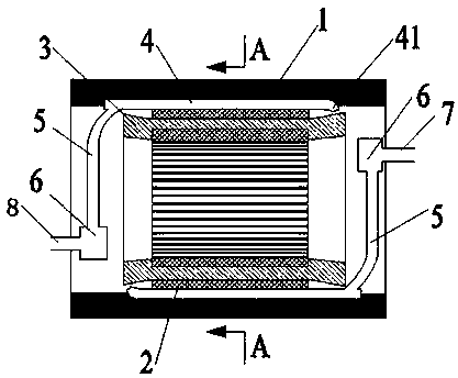
[0045] Such as figure 1 As shown, a motor stator and housing installation structure with a fuel injection pipe design according to the present invention includes a housing 1 and a stator core 2. The stator core 2 is installed in the housing 1, and the stator core 2 It is still installed with the housing 1 using the traditional thermal sleeve process, but there is no need to consider the issue of interference fit.

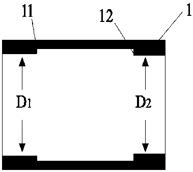
[0046] Such as image 3 As shown, the two ends of the inner surface of the housing 1 are respectively provided with a ring-shaped boss A11 and a ring-shaped boss B12, the ring-shaped boss A11 and the ring-shaped boss B12 are used to limit the stator core 2 Therefore, the inner diameter of the housing 1 at t...


PUM


Abstract

The invention relates to a motor stator and shell installation structure designed with spray bars and a design method for a spray bar. Compared with the prior art, the deficiency that the motor stator and shell installation structure cannot meet actual use requirements is solved. An annular bump A and an annular bump B are respectively arranged at two ends parts of the inner surface of the shell, the inner diameter of the shell positioned at the annular bump A is less than that of the shell positioned at the annular bump B, a plurality of grooves are arranged on the inner surface of the shell between the annular bump A and the annular bump B at equal intervals, and the grooves are parallel to the axial direction of the shell; the spray bars are placed in the grooves, an oil nozzle is arranged at one end of each spray bar, while an oil intake hose is connected with the other end of the spray bar, the oil intake hoses are connected with a right oil intake pipe via an oil intake tap, the spraying directions of the oil nozzles face to a winding at the end part of a stator iron core. According to the structure provided by the invention, the design method for an oil-cooling motor structure and the assembly technology of the stator shell are greatly simplified.

Description

Technical field [0001] The invention relates to the technical field of electric vehicle motors, in particular to a motor stator and housing installation structure with a fuel injection pipe design and a design method of the fuel injection pipe. Background technique [0002] With the rapid development of the electric vehicle industry, related technologies are also constantly improving. As the core component of electric vehicles, permanent magnet synchronous motors directly determine the performance of electric vehicles. [0003] In the field of new energy vehicles, the requirements for permanent magnet synchronous motors are getting higher and higher, and the motor power density is getting bigger and bigger. Heat dissipation has become the most important factor restricting the continuous increase of motor power density. At present, most permanent magnet synchronous motors for electric vehicles adopt a water-cooled structure, that is, the heat generated by the stator of the motor is...

Claims


Application Information

Patent Timeline
Patent Type & Authority Applications(China)
IPC IPC(8): H02K15/00H02K9/19H02K5/20
CPCH02K5/20H02K9/19H02K15/00
Inventor 刘蕾王体伟江超
Owner HEFEI JUYI POWER SYST CO LTD
Learn More