


Quick Research
Generate reliable direction feasibility study reports for your R&D in just a few steps.

Technical Q&A
Discover and master advanced knowledge NOW. Basics, ideas, possibilities, all at once.

Find Solutions
As an expert in R&D theories, this can generate solutions to your technical problems instantly.

Evaluate Feasibility
Analyze your overall solution with one click, know your potential R&D risks in advance.

Monitor Landscape
Get weekly tech updates, stay abreast of the latest tech innovations and key insights.
Filling type sheath-structure cable
A filling and sheathing technology, used in insulated cables, power cables, power cables including optical transmission components, etc., can solve the problems of general water blocking effect, short-circuit current transmission effect, large copper wire gap, etc., to achieve production efficiency The effect of not being affected, reducing production costs and increasing compressive strength
- Summary
- Abstract
- Description
- Claims
- Application Information
AI Technical Summary
Problems solved by technology
Method used
Image

Examples
Embodiment 1
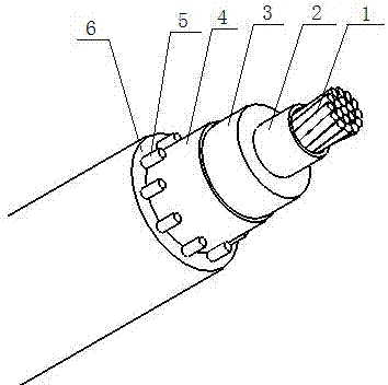
[0028] Such as figure 1 A cable with a filled sheath structure is shown, including a conductor 1, a conductor shielding layer 2, an insulating layer 3, an insulating shielding layer 4, a shielding layer 5, and a sheathing layer 6, and the conductor 1 is provided with a conductor shielding layer 2 , the conductor shielding layer 2 is provided with an insulating layer 3, the insulating layer 3 is provided with an insulating shielding layer 4, the insulating shielding layer 4 is provided with a shielding layer 5, and the shielding layer 5 is filled with a sheath Layer 6.
[0029] in:
[0030] Conductor 1 adopts one of aluminum conductors, aluminum alloy conductors, annealed copper conductors without metal plating, or other two types of conductors; conductor shielding layer 2 is made of extruded semi-conductive material or semi-conductive tape and extruded semi-conductive Conductive material; the insulating layer 3 is uniformly extruded on the conductor shielding layer by cross-...
Embodiment 2
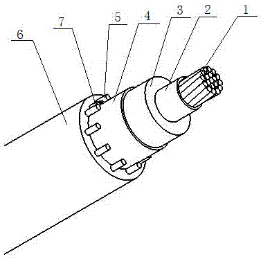
[0033] Such as figure 2 A filled sheath structure cable with photoelectric composite function is shown, including a conductor 1, a conductor shielding layer 2, an insulating layer 3, an insulating shielding layer 4, a shielding layer 5, and a sheathing layer 6, and the conductor 1 is peripherally equipped with There is a conductor shielding layer 2, an insulating layer 3 is arranged outside the conductor shielding layer 2, an insulating shielding layer 4 is arranged outside the insulating layer 3, a shielding layer 5 is arranged outside the insulating shielding layer 4, and a shielding layer 5 is arranged outside the insulating shielding layer 5 The gap is filled with a sheath layer 6, and the shielding layer 5 is provided with an optical unit 7 on the same layer. The optical unit 7 adopts an optical fiber and a stainless steel tube on the outer layer of the optical fiber. The stainless steel tube can effectively protect the optical fiber.
[0034] in:
[0035] Conductor 1 a...
Embodiment 3
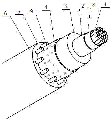
[0039] Such as image 3 A filled sheath structure cable with strong water blocking performance is shown, including conductor 1, conductor shielding layer 2, insulating layer 3, insulating shielding layer 4, shielding layer 5, sheath layer 6, semiconducting resistance water tape 8 and water blocking powder 9, the conductor 1 is provided with a conductor shielding layer 2, the conductor shielding layer 2 is provided with an insulating layer 3, the insulating layer 3 is provided with an insulating shielding layer 4, and the insulating shielding layer A shielding layer 5 is arranged on the outside of the shielding layer 5, and the gap of the shielding layer 5 is filled with a sheath layer 6.
[0040] in:
[0041] Conductor 1 is a water-blocking conductor. Conductor 1 can be one of aluminum conductors, aluminum alloy conductors, annealed copper conductors without metal plating, or other two types of conductors. The conductor center line and the conductor layer are all made of semi...
PUM
 Abstract
Description
Claims
Application Information
 - R&D Engineer
- R&D Manager
- IP Professional
- Industry Leading Data Capabilities
- Powerful AI technology
- Patent DNA Extraction
Browse by: Latest US Patents, China's latest patents, Technical Efficacy Thesaurus, Application Domain, Technology Topic, Popular Technical Reports.
© 2024 PatSnap. All rights reserved.Legal|Privacy policy|Modern Slavery Act Transparency Statement|Sitemap|About US| Contact US: help@patsnap.com