Glue injection machine

A technology of glue injection machine and glue injection mold, which is applied in the field of glue injection machine, can solve problems such as cable scrapping, damage to precision instruments and equipment, loss, etc., and achieve the effects of reliable use, improved work efficiency, and strong adaptability

Pending Publication Date: 2018-02-09
CHANGZHOU MARINE CABLE
View PDF0 Cites 0 Cited by
  • Summary
  • Abstract
  • Description
  • Claims
  • Application Information

AI Technical Summary

Problems solved by technology

However, for cables used in power and signal transmission in places such as military ships, civilian ships, underwater vehicles, marine detectors, water conservancy projects, and offshore oil platforms, as long as the outer sheath is slightly damaged, the water will flow along the cable. The length of the cable will seep into the cabin and into the equipment in large quantities. If seawater enters the cable, it will corrode the cable and cause the entire cable to be scrapped or even damage the precision equipment connected to the cable, causing great losses.

Method used


Image

  • Glue injection machine
  • Glue injection machine
  • Glue injection machine

Examples


Embodiment 1)

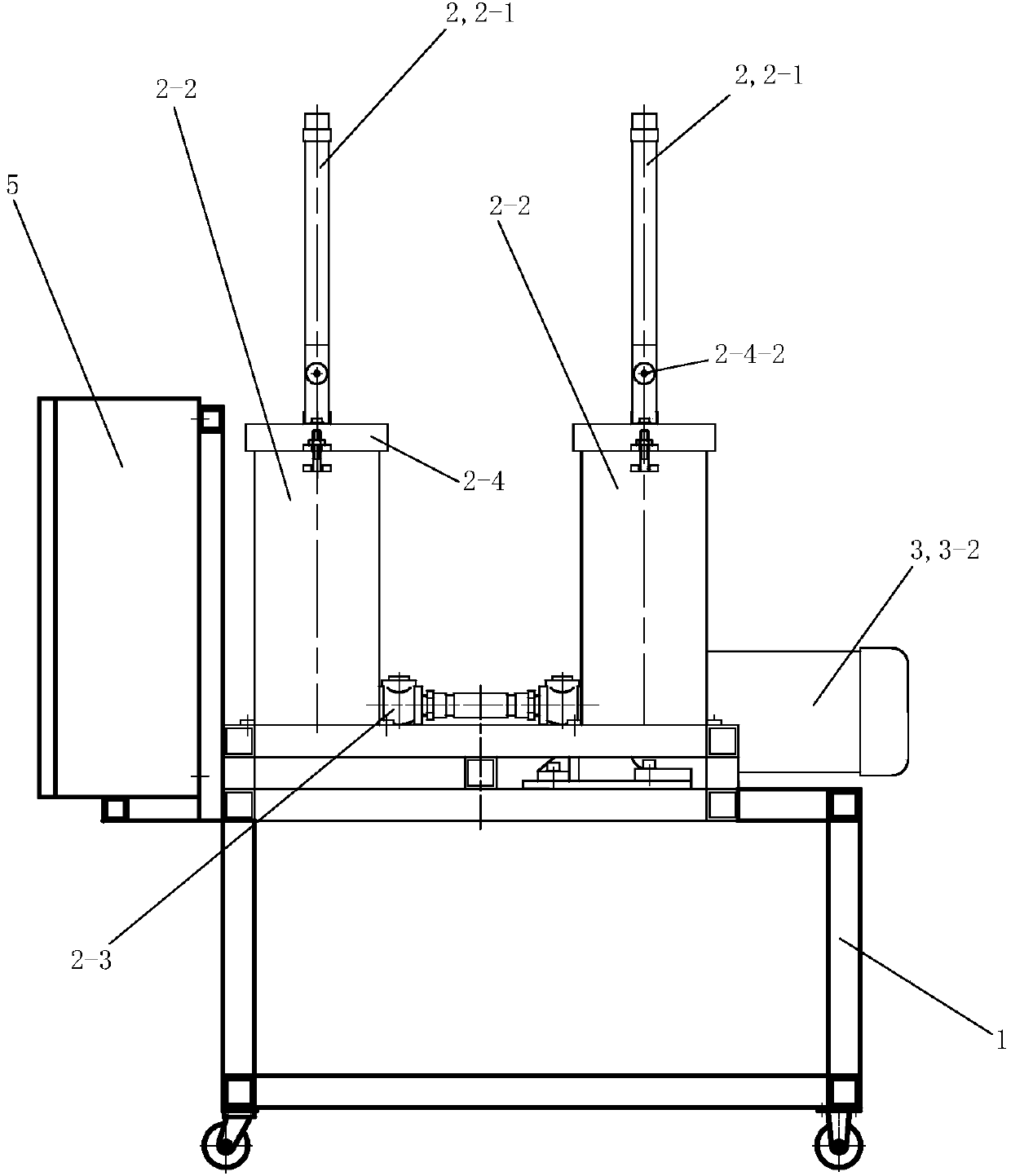
[0035] The description of the glue injection machine of the present embodiment follows figure 1 in the orientation shown, i.e. figure 1 The up, down, left, and right directions shown are the described up, down, left, and right directions. figure 1 The side facing is the front, and the side facing away from figure 1 One of the sides is the rear, and the orientation of the injection mold assembly is described in the photo Image 6 in the orientation shown, i.e. Image 6 The up, down, left, and right directions shown are the described up, down, left, and right directions. Image 6 The side facing is the front, and the side facing away from Image 6 One side is the rear.

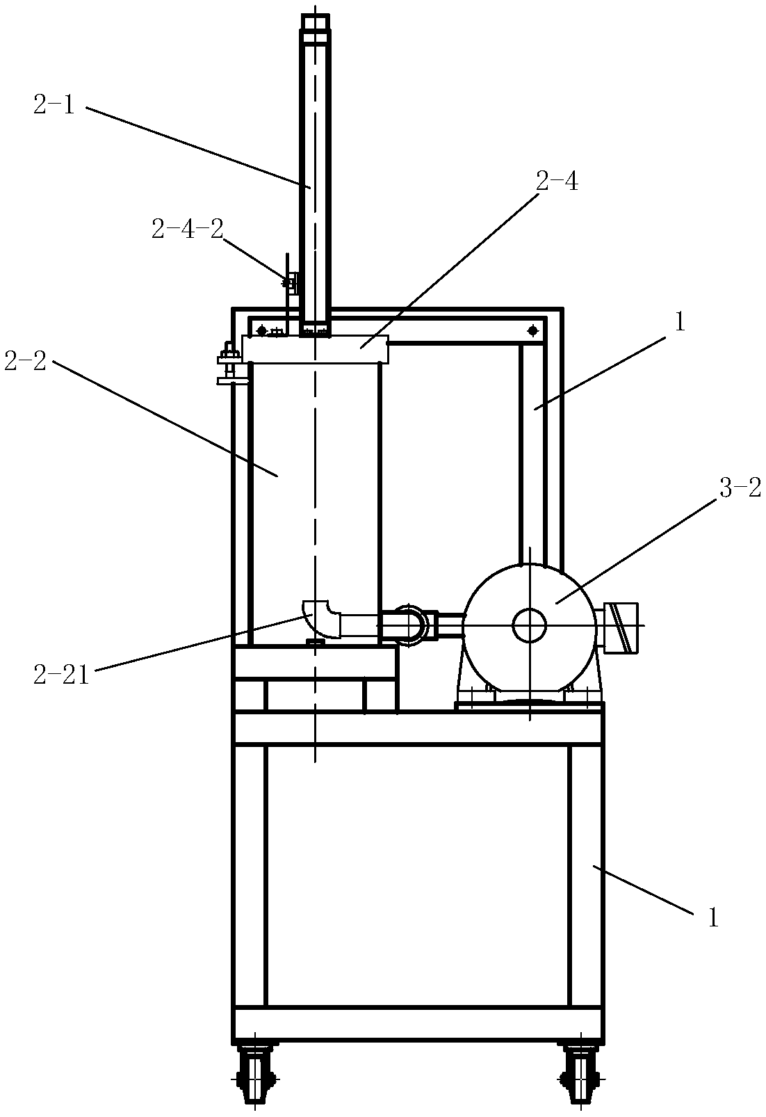
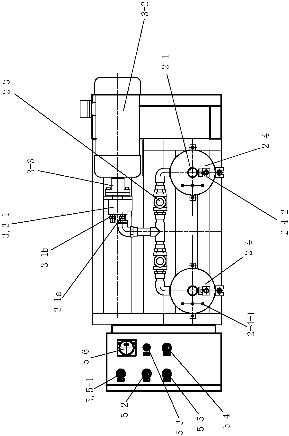
[0036] See Figure 1 to Figure 12 , The glue injection machine of the present invention includes a frame 1 , a glue feeding assembly 2 , a flow regulating assembly 3 , a glue injection mold assembly 4 and a control device 5 . The lower part of the frame 1 is provided with casters, which is convenient for ...

Embodiment 2)

[0041] The description of the glue injection machine of the present embodiment follows figure 1 in the orientation shown, i.e. figure 1 The up, down, left, and right directions shown are the described up, down, left, and right directions. figure 1 The side facing is the front, and the side facing away from figure 1 One of the sides is the rear, and the orientation of the injection mold assembly is described in the photo Figure 7 in the orientation shown, i.e. Figure 7 The up, down, left, and right directions shown are the described up, down, left, and right directions. Figure 7 The side facing is the front, and the side facing away from Figure 7 One side is the rear.

[0042] See Figure 7 to Figure 12 , The rest of this embodiment is the same as that of Embodiment 1, except that the injection mold assembly 4 also includes a liner 4-2, a deep groove ball bearing 4-3 and a pressure ring 4-4.

[0043] See Figure 7 to Figure 12 , Die cover 4-1 is a steel integral pie...


PUM


Abstract

The invention discloses a glue injection machine. The glue injection machine is characterized by comprising a rack, a glue conveying assembly, a flow adjustment assembly, a glue injection die assemblyand a control apparatus; the control apparatus is fixedly arranged on the left side of the upper part of the rack; the control apparatus is used for controlling operation of the glue injection machine; the glue injection die assembly comprises a die sleeve; a wire passing hole which runs through the left and right parts of the die sleeve is formed in the middle part of the die sleeve; the wire passing hole comprises a glue injection section and a wire outlet section; the glue injection section adopts a circular table shape with a big left part and a small right part; the right end of the glueinjection section and the left end of the wire outlet section are in smooth transition; a glue injection hole connected with the glue injection section of the wire passing hole is formed in the upperpart of the die sleeve; an annular glue injection groove with an inward opening is also formed in the glue injection section of the wire passing hole of the die sleeve; the glue injection groove is connected with the wire passing hole and the glue injection hole; and a gear pump glue outlet of a gear pump is connected with the glue injection hole of the die sleeve in a sealing manner through a corresponding pipeline and a pipe joint.

Description

technical field [0001] The invention relates to the field of power cables, in particular to a glue injection machine for cables. Background technique [0002] The common land cable used at present is to play a waterproof function through a complete outer sheath. However, for cables used in power and signal transmission in places such as military ships, civilian ships, underwater vehicles, marine detectors, water conservancy projects, and offshore oil platforms, as long as the outer sheath is slightly damaged, the water will flow along the cable. The length of the cable will seep into the cabin and into the equipment in large quantities. If seawater enters the cable, it will corrode the cable and cause the entire cable to be scrapped or even damage the precision equipment connected to the cable, causing great losses. Therefore, the cable is required to bear huge pressure and have good water resistance, so as to ensure that the cable can also have a certain water blocking eff...

Claims


Application Information

Patent Timeline
Patent Type & Authority Applications(China)
IPC IPC(8): H01B13/32
CPCH01B13/327
Inventor 殷垚新李作鹏曹小波
Owner CHANGZHOU MARINE CABLE
Why Eureka
Try Eureka