A meteorological radar rainfall detection and analysis system and method

A weather radar and analysis method technology, applied in radio wave measurement systems, measurement devices, climate sustainability and other directions, can solve problems such as target intensity display errors, affect detection results, affect flight safety, etc., achieve accurate and fast measurement, improve Accuracy and stability, safe guidance flight safety effect

Active Publication Date: 2021-02-19
LEIHUA ELECTRONICS TECH RES INST AVIATION IND OF CHINA
View PDF4 Cites 0 Cited by
  • Summary
  • Abstract
  • Description
  • Claims
  • Application Information

AI Technical Summary

Problems solved by technology

[0003] 1) Due to the inherent characteristics of the analog device, the parameters have certain volatility, resulting in a certain difference between the parameter values ​​​​used in the software and the actual control values
[0004] 2) There is a linear relationship between the parameter and the intensity, and the fluctuation value directly affects the detection result
[0005] 3) According to engineering experience, there is a ±3dB fluctuation in the system amplification gain, resulting in a change in the reflectivity factor of approximately ±3dBZ, and the division of the rainfall level mark, there is an error in the display of the target intensity, which may cause misjudgment by the crew and affect flight safety

Method used


Image

  • A meteorological radar rainfall detection and analysis system and method
  • A meteorological radar rainfall detection and analysis system and method
  • A meteorological radar rainfall detection and analysis system and method

Examples


Embodiment Construction

[0030] In order to make the objectives, technical solutions and advantages of the present invention clearer, the technical solutions in the embodiments of the present invention will be described in more detail below in conjunction with the drawings in the embodiments of the present invention. In the drawings, the same or similar reference numerals denote the same or similar elements or elements having the same or similar functions throughout. The described embodiments are some, but not all, embodiments of the invention. The embodiments described below by referring to the figures are exemplary and are intended to explain the present invention and should not be construed as limiting the present invention. Based on the embodiments of the present invention, all other embodiments obtained by persons of ordinary skill in the art without creative efforts fall within the protection scope of the present invention. Embodiments of the present invention will be described in detail below ...


PUM


Abstract

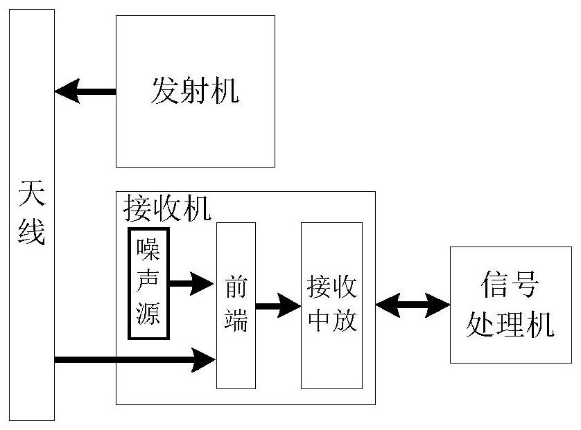
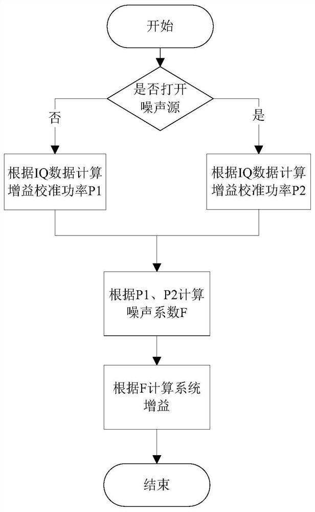
The invention discloses a weather radar rainfall detection and analysis system and method, belonging to the detection field of airborne weather radars. The front end of the receiver is provided with a noise source; the noise source can output signals stably, the main control unit of the signal processor controls the opening and closing of the noise source, and the digital signal processing unit of the signal processor records the noise source opening and closing respectively The AD sampling data at the time is calculated and processed to obtain the gain value of the receiving channel. Based on the method of the meteorological radar rainfall detection and analysis system, step 1, turn off the noise source, and calculate the gain calibration power P according to the IQ data of the sampling module 1 ; Step 2, turn on the noise source, and calculate the gain calibration power P according to the IQ data 2 ; Step three, calculate the noise figure F; Step four, calculate the gain G of the receiving channel; Step five, process the calculated receiving channel gain G; can accurately measure the channel gain, and eliminate the impact of the channel gain error on the accuracy and stability of meteorological detection sexual influence.

Description

technical field [0001] The invention belongs to the technical field of airborne weather radar detection, and in particular relates to a weather radar rainfall detection and analysis system and method. Background technique [0002] At present, the design of airborne weather radar does not introduce real-time measurement and calibration of channel gain. The channel gain value used in signal processing is only a single test result measured in the laboratory or during the flight test. Therefore, for rainfall The detection results have the following effects: [0003] 1) Due to the inherent characteristics of the analog device, the parameters have certain volatility, resulting in a certain difference between the parameter values ​​​​used in the software and the actual control values. [0004] 2) The parameter has a linear relationship with the intensity, and the fluctuation value directly affects the detection result. [0005] 3) According to engineering experience, there is a ±...

Claims


Application Information

Patent Timeline
Patent Type & Authority Patents(China)
IPC IPC(8): G01S13/95G01S7/41
CPCG01S7/414G01S13/953Y02A90/10
Inventor 孟凡旺孟子塬周楠
Owner LEIHUA ELECTRONICS TECH RES INST AVIATION IND OF CHINA
Why Eureka
Try Eureka