A kind of turbulence type multi-fluid integrated mixer
A mixer, multi-fluid technology, applied in the direction of machine/engine, charging system, mechanical equipment, etc., can solve the problems of low integration degree and poor mixing effect, achieve high integration degree, good effect and improve utilization rate Effect
- Summary
- Abstract
- Description
- Claims
- Application Information
AI Technical Summary
Problems solved by technology
Method used
Image

Examples
Embodiment 1
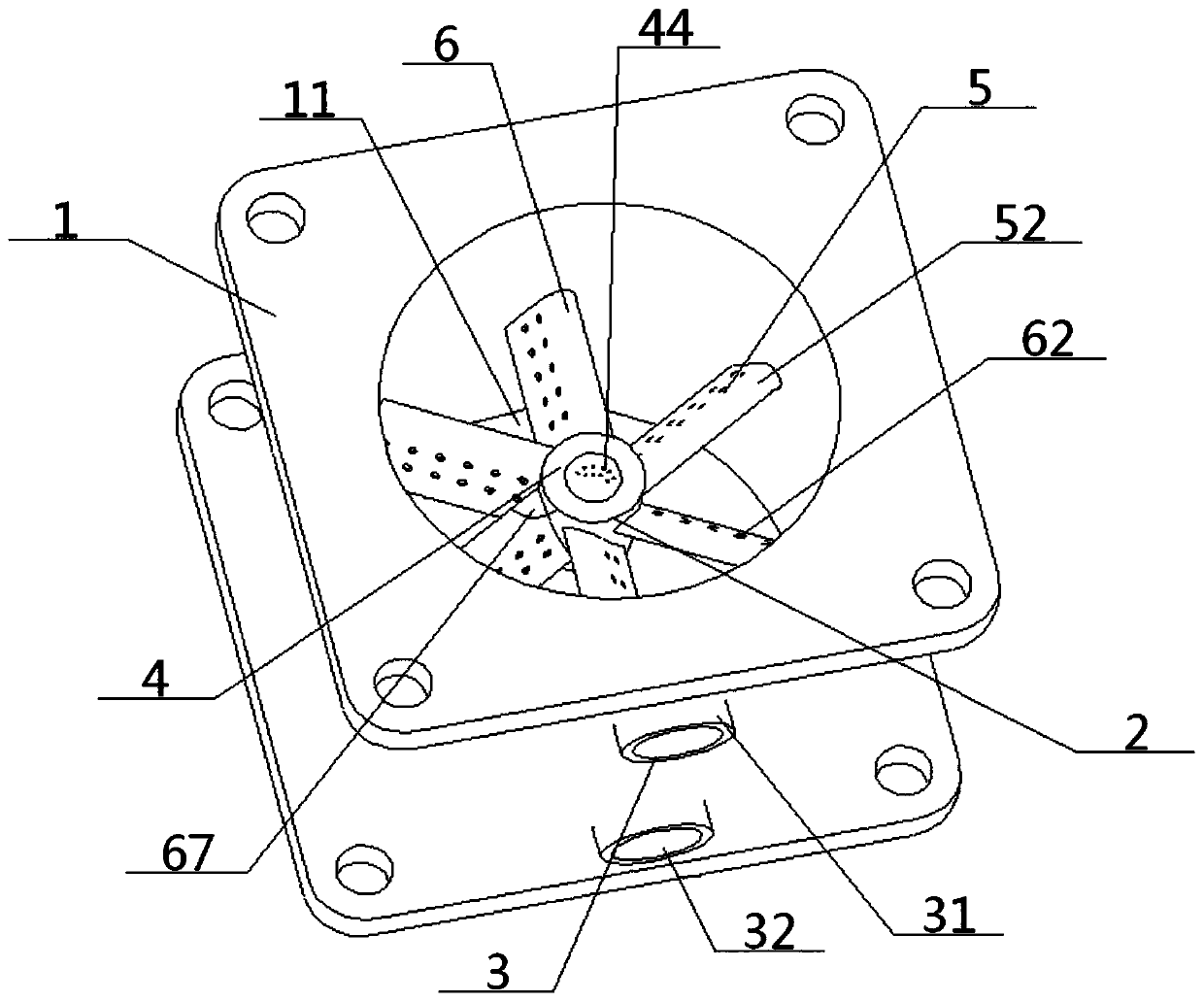
[0056] see Figure 1 to Figure 12 , a turbulent flow multi-fluid integrated mixer, comprising a mixer main body 1, a mixing core 2 and an air inlet 3, the air inlet 3 is connected to the outer wall of the mixer main body 1, and the middle part of the mixer main body 1 is opened There is a through main channel 11, and the middle part of the main channel 11 is provided with a mixing core 2, and the mixing core 2 communicates with the air inlet 3 through the main cavity 12 opened in the mixer main body 1;
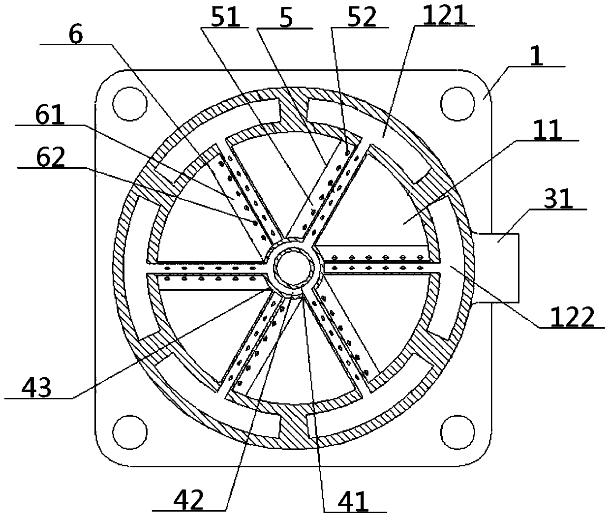
[0057] The air inlet 3 includes a fluid A inlet 31 and a fluid B inlet 32 arranged up and down, and the mixing core 2 includes a central fixture 4, a fluid A vane 5 and a fluid B vane 6, and the fluid A vane 5, the fluid B vane The interior of the blade 6 is correspondingly provided with a sheet A cavity 51 and a sheet B cavity 61; the inner ends of the fluid A blade 5 and the fluid B blade 6 are connected to the side of the central fixture 4, and the fluid A blade 5 and the...
Embodiment 2
[0059] Basic content is the same as embodiment 1, the difference is:
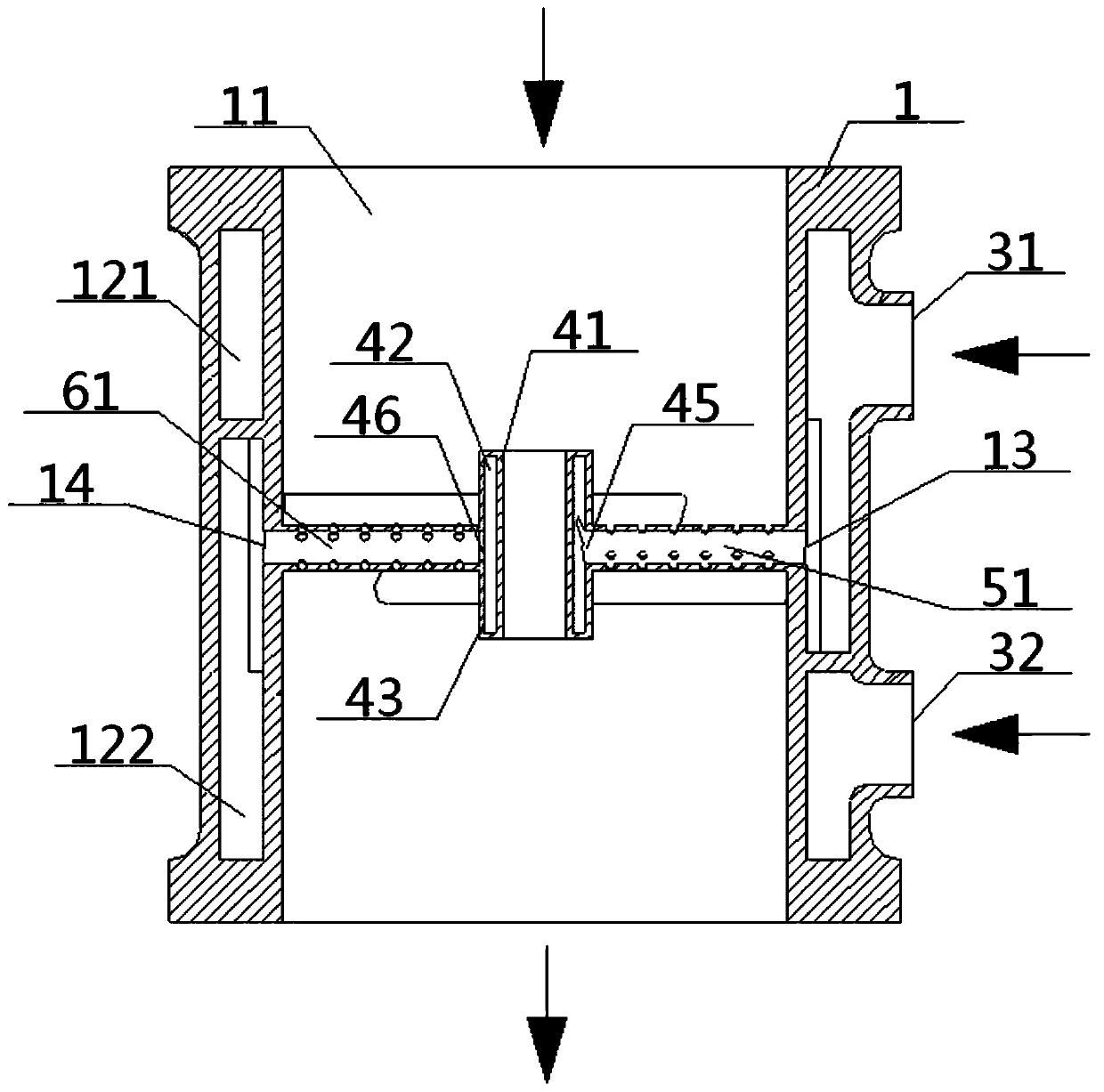
[0060] The central fixing member 4 is a cylindrical hollow structure, which sequentially includes an inner cylinder wall 41, a middle cylinder chamber 42 and an outer cylinder wall 43 from the inside to the outside. The inner cylinder wall 41 is provided with a plurality of central air outlet holes 44, and the outer cylinder A fluid A socket 45 and a fluid B socket 46 are opened on the wall 43 to connect with the inner ends of the corresponding fluid A vane 5 and fluid B vane 6 . The two ends of described piece A cavity 51 communicate with middle tube cavity 42, main cavity 12 respectively, the inner end of described piece B cavity 61 is not connected with middle tube cavity 42, the outer end of piece B cavity 61 communicates with main cavity body. 12 connected.
Embodiment 3
[0062] Basic content is the same as embodiment 1, the difference is:
[0063] The structure of the fluid A blade 5 and the fluid B blade 6 is consistent, and the fluid B blade 6 includes a left side 63, a top arc surface 64, a right side 65 and a bottom arc surface 66 connected in sequence, and the top arc surface 64. The bottom curved surface 66 is arc-shaped, the top curved surface 64 is wider than the bottom curved surface 66, and a plurality of fluid B air outlets 62 are opened on the left side 63 and the right side 65. The upper and lower ends of the left side 63 are respectively an upper left arc 631 and a lower left arc 632, and the upper and lower ends of the right side 65 are respectively an upper right arc 651 and a lower right arc 652, and an upper left arc 631, The lower left arc 632, the upper right arc 651, and the lower right arc 652 are all arc structures, and the arcs of the upper left arc 631 and the upper right arc 651 are different, and the arcs of the lowe...
PUM
 Abstract
Description
Claims
Application Information
 - Generate Ideas
- Intellectual Property
- Life Sciences
- Materials
- Tech Scout
- Unparalleled Data Quality
- Higher Quality Content
- 60% Fewer Hallucinations
Browse by: Latest US Patents, China's latest patents, Technical Efficacy Thesaurus, Application Domain, Technology Topic, Popular Technical Reports.
© 2025 PatSnap. All rights reserved.Legal|Privacy policy|Modern Slavery Act Transparency Statement|Sitemap|About US| Contact US: help@patsnap.com