
Correctable imaging laser radar receiver and signal processing method

A technology of laser radar and receiver, which is applied in the direction of instruments, measuring devices, and re-radiation, can solve the problems of difficult debugging, distortion of reconstructed image intensity information, and long imaging time, so as to eliminate the mismatch of photoelectric gain and simplify the back end Signal processing, the effect of meeting the sensitivity requirements

Active Publication Date: 2017-11-07
西安芯辉光电科技有限公司
View PDF4 Cites 3 Cited by
  • Summary
  • Abstract
  • Description
  • Claims
  • Application Information

AI Technical Summary

Problems solved by technology

These three imaging methods have their own advantages and disadvantages. Among them, the single-channel two-dimensional scanning imaging radar technology is relatively mature. The front-end analog circuit for photodetectors is usually designed with separate devices, which are often used for laser ranging. In imaging radar applications, imaging time is faced. Too long, poor imaging quality, bulky system structure and many other problems, the application is limited; people turn to look for detectors with more pixels, such as line array and area array detectors. Large, the design of the receiver analog front-end circuit faces the following challenges: the discrete device design array receiver analog front-end circuit encounters the following technical bottlenecks, such as: the use of discrete device design will lead to high system power consumption and reduced circuit reliability. Difficulty in debugging and other insurmountable problems, so the array receiver analog front-end circuit adopts advanced integrated circuit design has become a trend; There is an inherent mismatch in the gain between the receiver channels. In the 3D imaging lidar receiver, the gain mismatch between the photoelectric detection devices will cause the echo intensity detection error between the receiver channels, resulting in distortion of the reconstructed image intensity information. Causes difficulty in target identification, limiting the application of linear mode photodetectors in array receivers

Method used


Image

  • Correctable imaging laser radar receiver and signal processing method
  • Correctable imaging laser radar receiver and signal processing method
  • Correctable imaging laser radar receiver and signal processing method

Examples


Embodiment 1

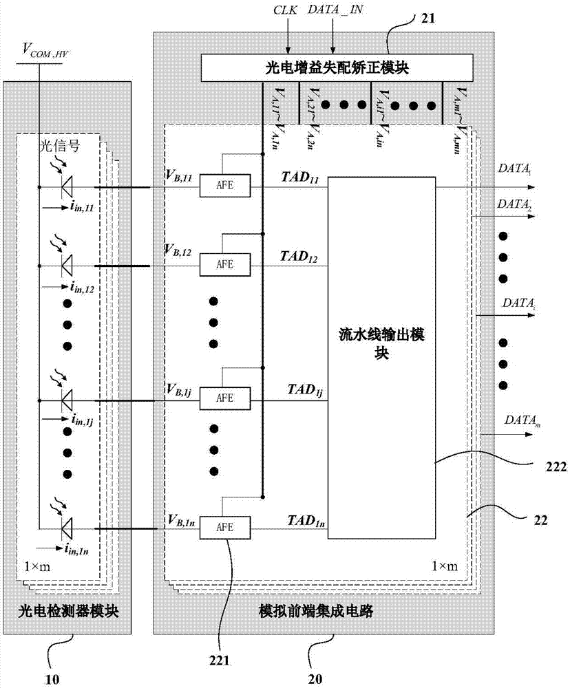
[0051] See figure 1 , figure 1 A circuit schematic diagram of a correctable imaging laser radar receiver provided for an embodiment of the present invention; the correctable imaging laser radar receiver includes:

[0052] The photodetector module 10 is used to convert the received optical signal into an electrical signal i in,11 ~i in,mn ;

[0053] Wherein, the photoelectric detection module 10 is used to convert the pulse light signal reflected back by the target into a pulse current signal.

[0054] High voltage common mode level terminal V COM,HV , electrically connected to the input end of the photodetector module 10, for providing a voltage source to the photodetector module 10;

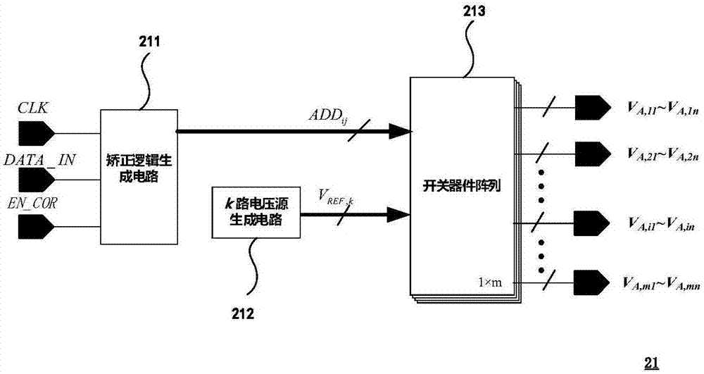
[0055] An analog front-end integrated circuit 20, electrically connected to the output terminal of the photodetector module 10, for converting the electrical signal i in,11 ~i in,mn Convert to digital signal DATA 1 ~DATA m , and includes an optical gain mismatch correction module 21 and...


PUM


Abstract

The present invention relates to a correctable imaging laser radar receiver. The receiver comprises: a photoelectric detector module (10) configured to receive optical signals and convert optical signals to electrical signals (iin, 11~iin, mn); a high-voltage common mode level end (VCOM, HV) electrically connected with the input end of the photoelectric detector module (10) and configured to provide a voltage source for the photoelectric detector module (10); and an analog front-end integration circuit (20) electrically connected with the output end of the photoelectric detector module (10), configured to convert the electrical signals (iin, 11~iin, mn) to digital signals (DTA1~DATAm) and consisting of a photocurrent gain mismatching correction module (21) and a plurality of analog front-end signal processing circuits (22), wherein each output end of the photocurrent gain mismatching correction module (21) is correspondingly and electrically connected with each analog front-end signal processing circuit (22). The photoelectric detector reverse bias voltage correction method is employed to effectively eliminate the echo intensity signal detection errors caused by photocurrent gain mismatching.

Description

technical field [0001] The invention belongs to the technical field of TOF imaging laser radar, and in particular relates to a correctable imaging laser radar receiver and a signal processing method. Background technique [0002] Time-of-flight (TOF) imaging lidar uses a distance sensor to obtain a distance image of the target surface to measure the geometric shape of the target surface. Each pixel of the distance image corresponds to the three-dimensional coordinates of the target surface, thus forming a three-dimensional image of the target. . In order to improve the recognition of each pixel in the image and facilitate the recognition of the target, on the basis of laser three-dimensional imaging, the receiver is required to be able to detect the intensity of light radiation reflected from the target surface, so as to increase the intensity of the target while reconstructing the three-dimensional image of the target. The image intensity information of the target. [000...

Claims


Application Information

Patent Timeline
Patent Type & Authority Applications(China)
IPC IPC(8): G01S7/486G01S17/89
CPCG01S7/4863G01S7/4866G01S17/89
Inventor 朱樟明郑浩马瑞刘马良杨银堂
Owner 西安芯辉光电科技有限公司
Learn More