
A continuous engine leak detection device and method with replaceable clamps

A technology for an engine and an engine casing, which is applied to the field of a continuous engine leak detection device with replaceable clamps, can solve the problems of increased equipment investment and maintenance costs, inflexible use of the leak detection device, and high investment cost of the leak detection device, and achieves a shortened time. Leak detection cycle, avoid false detection phenomenon, low maintenance cost effect

Active Publication Date: 2019-06-21
广州市嘉特斯机电制造有限公司
View PDF7 Cites 0 Cited by
  • Summary
  • Abstract
  • Description
  • Claims
  • Application Information

AI Technical Summary

Problems solved by technology

In the current leak detection device, the fixture used to clamp the engine workpiece on the detection station is fixed and cannot be replaced. Therefore, each leak detection device can only be used for leak detection of engines of the same specification and model, and the detection station generally needs to be equipped with a crankshaft. There are multiple stations such as tank leak detection station and oil water channel leak detection station. For manufacturers of large-scale production of engines, the investment cost of leak detection devices is quite high, which is not conducive to the control of production costs. In addition, every time a production Engines of various specifications and models must be equipped with a leak detection device, which greatly increases equipment investment and maintenance costs, and occupies a large area. The use of the leak detection device is not flexible enough, and the utilization rate is difficult to improve.

Method used


Image

  • A continuous engine leak detection device and method with replaceable clamps
  • A continuous engine leak detection device and method with replaceable clamps
  • A continuous engine leak detection device and method with replaceable clamps

Examples


Embodiment 1

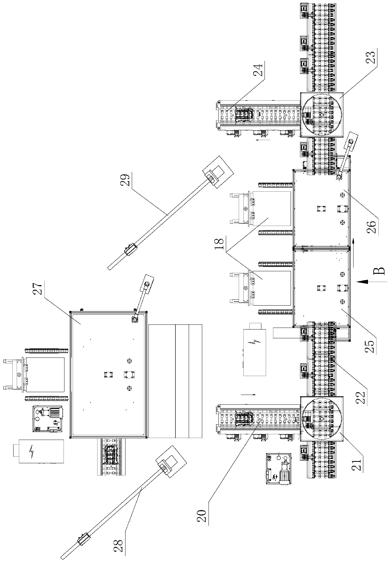
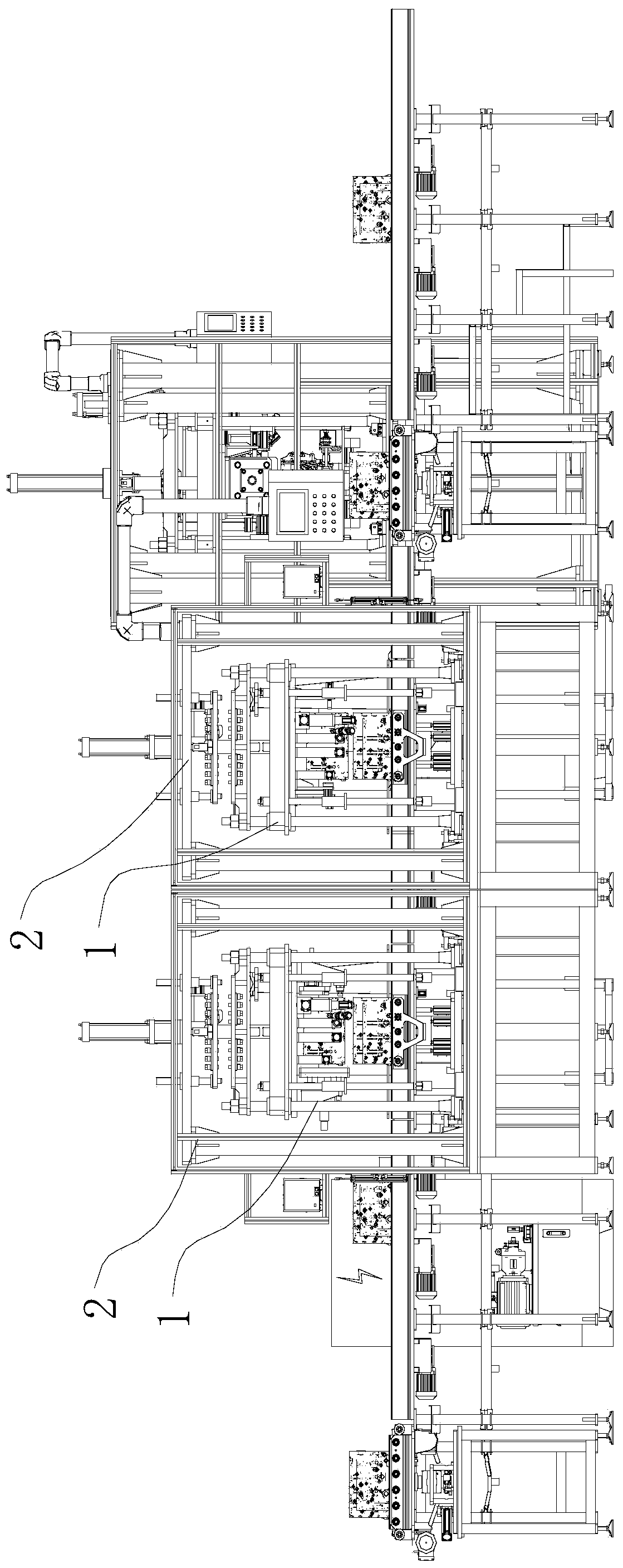
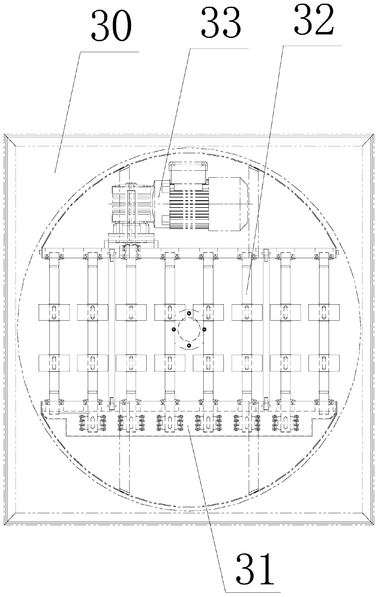
[0044] In this embodiment, a continuous engine leak detection device with replaceable clamps, such as figure 1 As shown, it includes the feeding raceway 20, the first turntable 21, the conveying raceway 22, the second turntable 23 and the discharge raceway 24 connected in sequence, and the crankcase leak detection station 25 and the oil and water channel inspection station are arranged on the conveying raceway. Leak station 26, a leak detection water tank 27 is arranged between the feed raceway and the discharge raceway, a first cantilever crane 28 is arranged between the feed raceway and the leak detection water tank, A second cantilever crane 29 is arranged between them; wherein, the first turntable and the second turntable are used for the conversion of the conveying direction of the engine case, and the crankcase leak detection station is used to detect whether the crankcase part of the engine case will leak, The oil and water channel leak detection station is used to dete...

Embodiment 2

[0054] In this embodiment, a continuous engine leak detection method with replaceable clamps is implemented by the device described in Embodiment 1, including the following steps:

[0055] (1) The engine casing as the workpiece enters from the feeding raceway, and enters the conveying raceway after passing through the first turntable;

[0056] (2) After the engine casing is sent to the crankcase leak detection station by the conveying raceway, it is clamped by the clamp on the crankcase leak detection station, and the engine casing is checked by a leak detector externally connected to the crankcase leak detection station. Carry out crankcase leak detection;

[0057] (3) After the crankcase leak detection is completed, the engine casing is sent to the oil and water channel leak detection station by the conveying raceway, and is clamped by the fixture on the oil and water channel leak detection station, and is connected to the oil and water channel leak detection station. The l...


PUM


Abstract

The present invention discloses a clamp replaceable continuous engine leakage detection device and method, wherein the device comprises a feeding raceway, a first rotary table, a conveying raceway, a second rotary table and a discharging raceway which are connected orderly. The conveying raceway is equipped with a crankcase leakage detection station and an oil-water way leakage detection station, a leakage detection water tank is arranged between the feeding raceway and the discharging raceway, and the crankcase leakage detection station and the oil-water way leakage detection station are equipped with the replaceable clamps and the clamp installing racks respectively. The method is characterized by conveying an engine shell via the feeding raceway, the conveying raceway and the discharging raceway, detecting the leakage at multiple parts continuously, when the type of the engine shell changes, being able to replace the clamps at the crankcase leakage detection station and the oil-water way leakage detection station, so that the leakage detection device can adapt to the leakage detection of the engines of multiple specifications and types, the usage flexibility of the leakage detection device is improved, and the equipment cost is reduced effectively.

Description

technical field [0001] The invention relates to the technical field of engine leak detection, in particular to a continuous engine leak detection device and method with replaceable clamps. Background technique [0002] In the automotive field, engine leakage failure is a relatively common and dangerous phenomenon. In order to ensure the normal operation of the engine during use, after the engine casing is manufactured, it is generally necessary to perform a leak test on it. Due to the variety of engine models and specifications, the fixture structures that need to be equipped in the leak detection process are also different. In the current leak detection device, the fixture used to clamp the engine workpiece on the detection station is fixed and cannot be replaced. Therefore, each leak detection device can only be used for leak detection of engines of the same specification and model, and the detection station generally needs to be equipped with a crankshaft. There are mult...

Claims


Application Information

Patent Timeline
Patent Type & Authority Patents(China)
IPC IPC(8): G01M3/02
CPCG01M3/025
Inventor 林茂源
Owner 广州市嘉特斯机电制造有限公司
Learn More