


Quick Research
Generate reliable direction feasibility study reports for your R&D in just a few steps.

Technical Q&A
Discover and master advanced knowledge NOW. Basics, ideas, possibilities, all at once.

Find Solutions
As an expert in R&D theories, this can generate solutions to your technical problems instantly.

Evaluate Feasibility
Analyze your overall solution with one click, know your potential R&D risks in advance.

Monitor Landscape
Get weekly tech updates, stay abreast of the latest tech innovations and key insights.
Seepage water blocking structure and heat exchange structure
A technology of blocking water and seepage, applied in the field of geothermal system, can solve problems such as failure to work normally, and achieve the effect of reducing seepage speed
- Summary
- Abstract
- Description
- Claims
- Application Information
AI Technical Summary
Problems solved by technology
Method used
Image


Examples
Embodiment 1
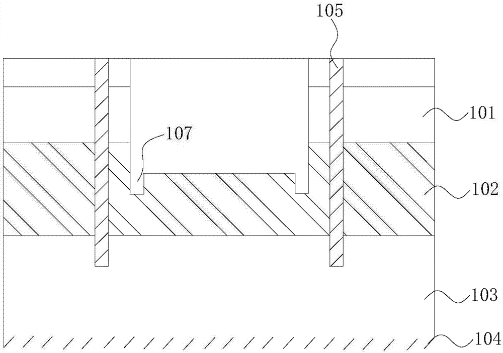
[0054] refer to figure 1 with figure 2 , the present embodiment provides a seepage water blocking structure for installation on a terrain, including a precipitation well 105 and an annular enclosure structure 106, and the terrain includes a submerged layer 101 and an aquitard 102 arranged from top to bottom , the confined water layer 103 and the water-resistant layer 104, the precipitation well 105 passes through the submerged layer 101 and the aquitard 102 to communicate with the confined water layer 103, the enclosure structure 106 is installed in the precipitation well 105, and the enclosure structure 106 is connected to the The precipitation wells 105 are arranged at intervals, and the bottom of the enclosure layer is installed on the aquitard 102 .
[0055] The seepage and water blocking structure provided in this embodiment utilizes the enclosure structure 106 and the dewatering well 105, and the seepage velocity is greater than 4×10 -7 The m / s soil is transformed, an...
Embodiment 2
[0062] refer to Figure 3 to Figure 5 , this embodiment also provides a seepage water blocking structure, this embodiment is a further improvement on the basis of the technical solution of embodiment 1, the technical solution described in embodiment 1 is also applicable to this embodiment, embodiment 1 has The disclosed technical solutions will not be described repeatedly.
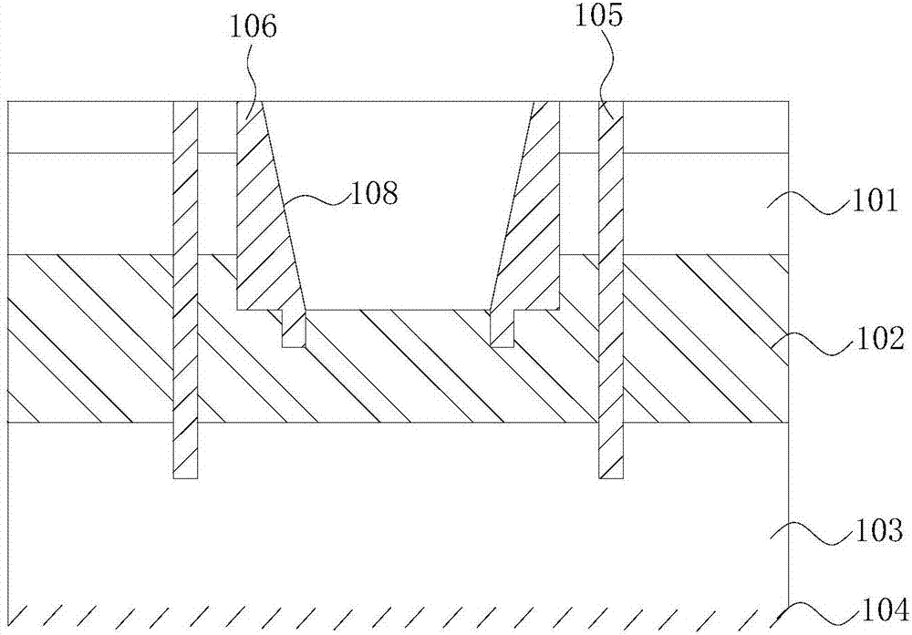
[0063] Specifically, the difference between this embodiment and Embodiment 1 is that the cross-sectional area of the top of the through hole of the seepage water blocking structure provided by this embodiment is larger than the cross-sectional area of the bottom of the through hole.
[0064] The structure that the cavity is large at the top and small at the bottom can greatly improve the heat transfer efficiency, thereby improving the working efficiency of the energy pile 112 .
[0065] The enclosure structure 106 is provided with a slope 108 , and the slope 108 is inclined inwardly from the top of th...
Embodiment 3
[0068] refer to Image 6 with Figure 7 , this embodiment also provides a seepage water blocking structure, this embodiment is a further improvement on the basis of the technical solution of embodiment 1, the technical solution described in embodiment 1 is also applicable to this embodiment, embodiment 1 has The disclosed technical solutions will not be described repeatedly.
[0069] Specifically, the difference between this embodiment and Embodiment 1 is that the enclosure structure 106 provided in this embodiment also includes a mounting piece 111, the installation piece 111 is located between the inclined surface 108 and the block 109, and the installation piece 111 is along the enclosure structure 106 The circumference is circular.
[0070] When excavating the groove 107 on the impermeable layer 102, some defects in the structure of the groove 107 can be avoided. The setting of the mounting sheet 111 can cover these defects, avoiding the impact of energy due to potholes ...
PUM
 Abstract
Description
Claims
Application Information
 - R&D Engineer
- R&D Manager
- IP Professional
- Industry Leading Data Capabilities
- Powerful AI technology
- Patent DNA Extraction
Browse by: Latest US Patents, China's latest patents, Technical Efficacy Thesaurus, Application Domain, Technology Topic, Popular Technical Reports.
© 2024 PatSnap. All rights reserved.Legal|Privacy policy|Modern Slavery Act Transparency Statement|Sitemap|About US| Contact US: help@patsnap.com