
Novel plunger pump

A plunger pump, a new type of technology, applied in the direction of piston pump, pump, pump control, etc., can solve the problems of cam pair wear, lateral wear, loss of feed accuracy, etc., to improve the effect of advection output, stable movement speed, and service life. long effect

Inactive Publication Date: 2017-11-07
殷图源
View PDF6 Cites 15 Cited by
  • Summary
  • Abstract
  • Description
  • Claims
  • Application Information

AI Technical Summary

Problems solved by technology

However, the constant flow pump with this structure is not suitable for long-term constant flow occasions. Long-term operation is likely to cause wear of the cam pair and fatigue of the return spring.
At the same time, because the cam transmission has a certain pressure angle, it will also cause lateral wear and loss of feeding accuracy. The characteristics of the HPLC industry can use thinner pipelines, but in other industries, it often causes a series of problems such as blockage.

Method used


Image

  • Novel plunger pump
  • Novel plunger pump
  • Novel plunger pump

Examples


Embodiment Construction

[0022] The principles and features of the present invention are described below in conjunction with the accompanying drawings, and the examples given are only used to explain the present invention, and are not intended to limit the scope of the present invention.

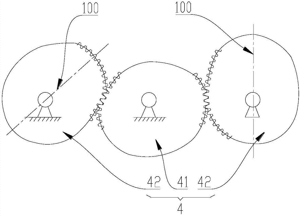
[0023] Such as Figure 1 to Figure 4 as shown, figure 1 A structural schematic diagram of a specific embodiment of a novel plunger pump provided by the present invention; figure 2 is a schematic structural view of the power transmission assembly 4; image 3 for figure 1 Partial assembly schematic diagram of the specific embodiment shown; Figure 4 for figure 1 Schematic illustration of a partial explosion of the specific embodiment shown.

[0024] In the specific embodiment of a new type of plunger pump provided by the present invention, it includes a driving device 1 and a pump body 2, and is characterized in that it also includes a power actuator assembly 3 and a power transmission assembly 4; the power actu...


PUM


Abstract

The present invention relates to a new type of plunger pump, which includes a driving device, a pump body, a power actuator assembly, and a power transmission assembly; the power actuator assembly includes a guide rod, a chute, and a swing plate that reciprocate in the pump body; The chute is fixedly mounted on one end of the guide rod protruding from the pump body, and the inner side of the chute has two parallel and opposite working planes, the working planes are perpendicular to the guide rod; The power transmission assembly includes an active non-circular gear and a passive non-circular gear meshing with each other, the passive non-circular gear is in transmission connection with the oscillating plate, the active non-circular gear is connected with the driving device, and is driven by the driving device its spinning. The plunger pump can realize the transmission of the sinusoidal mechanism, the pressure angle can be realized by the rotation of the chute and the oscillating disk, and the non-circular gear can realize the smooth movement speed of the guide rod. The equipment is driven by non-circular gears, which can greatly overcome many shortcomings of the cam mechanism, and has a long service life and is not easy to wear.

Description

technical field [0001] The invention relates to a liquid power delivery device, in particular to a novel plunger pump. Background technique [0002] In recent years, the preparative chromatography industry and the supercritical industry have developed rapidly. The development needs of the traditional petrochemical industry, especially the high-pressure fracturing pumps in shale oil fields, require high-pressure plunger pumps with large flow and non-pulsating transport of chemical media, with a pressure range of 5MPa to 100MPa. The flow range is divided into two levels: small flow area laboratory type, 0.01 ~ 500m L / min; large flow industrial manufacturing type, 0.5 ~ 50L / min. The transmission medium is water, methanol, acetone, propylene, butane, liquid carbon dioxide, etc. Generally, no pulse transmission is required for system stability. In the laboratory and other small flow areas, the cam structure transmission device plunger pump constant flow pump is mainly used at pr...

Claims


Application Information

Patent Timeline
IPC IPC(8): F04B9/02F04B17/03F04B49/20F16H37/12
CPCF04B9/02F04B17/03F04B49/20F16H37/124
Inventor 殷图源
Owner 殷图源
Learn More