
Coaxial direct-current plasma nozzle based on dielectric barrier discharge

A dielectric barrier discharge and plasma technology, applied in jet propulsion devices, rocket engine devices, machines/engines, etc., can solve problems such as narrow control range, difficult nozzle atomization, insufficient mixing of fuel and oxidant jets, etc.

Active Publication Date: 2017-11-07
PLA PEOPLES LIBERATION ARMY OF CHINA STRATEGIC SUPPORT FORCE AEROSPACE ENG UNIV
View PDF7 Cites 10 Cited by
  • Summary
  • Abstract
  • Description
  • Claims
  • Application Information

AI Technical Summary

Problems solved by technology

[0006] 1. The fuel sprayed out of the nozzle is not sufficiently mixed with the oxidant jet, and the ignition condition cannot be directly achieved, and an additional ignition device needs to be added near the nozzle outlet
[0007] 2. The atomization quality of the liquid jet sprayed from the nozzle is not high; when the engine is working under non-design conditions, it is difficult to maintain the optimal atomization and mixing performance of the nozzle in a wide range only by adjusting the flow rate and temperature of the propellant
[0008] 3. Under certain working conditions, the nozzle will stimulate the combustion instability of the entire engine; when combustion instability occurs, it can only be controlled by mechanical methods such as adjusting the flow rate, with slow response and narrow control range
[0009] 4. Nozzle performance drops sharply under variable working conditions and wide range of conditions

Method used


Image

  • Coaxial direct-current plasma nozzle based on dielectric barrier discharge
  • Coaxial direct-current plasma nozzle based on dielectric barrier discharge
  • Coaxial direct-current plasma nozzle based on dielectric barrier discharge

Examples


Embodiment Construction

[0050] The present invention will be further described in detail below in conjunction with the accompanying drawings and specific preferred embodiments.

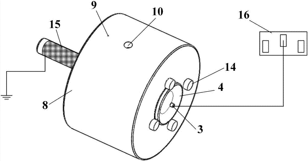
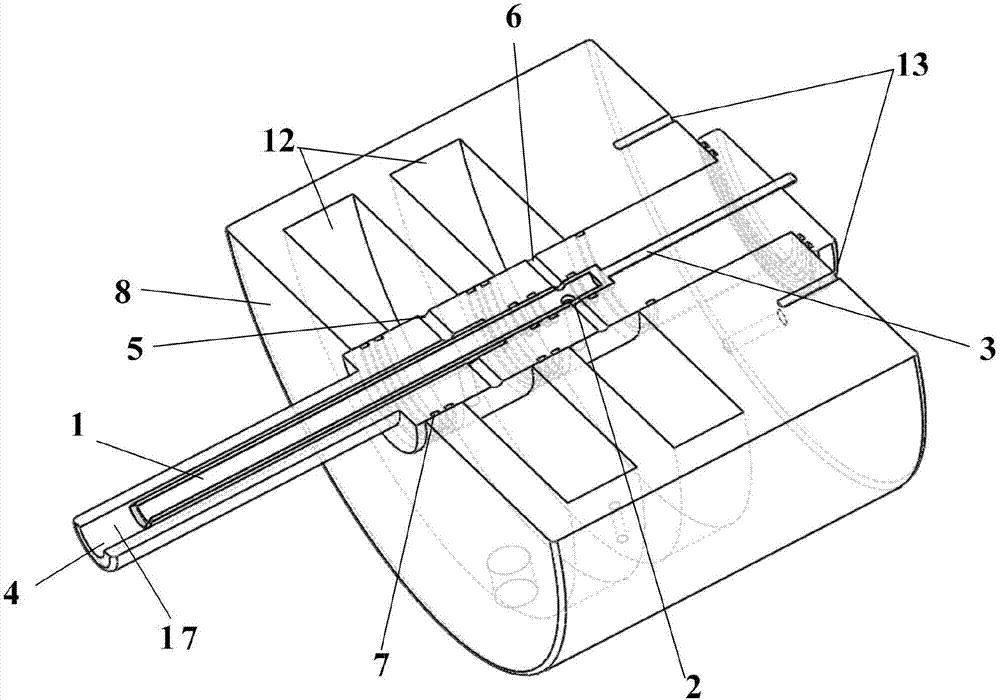
[0051] Such as figure 1 and figure 2 As shown, a coaxial direct current plasma nozzle based on dielectric barrier discharge includes a metal inner cylinder 1 , a metal rod 3 , an insulating outer cylinder 4 , a propellant chamber 8 , an outer electrode 15 and a high voltage power supply 16 .

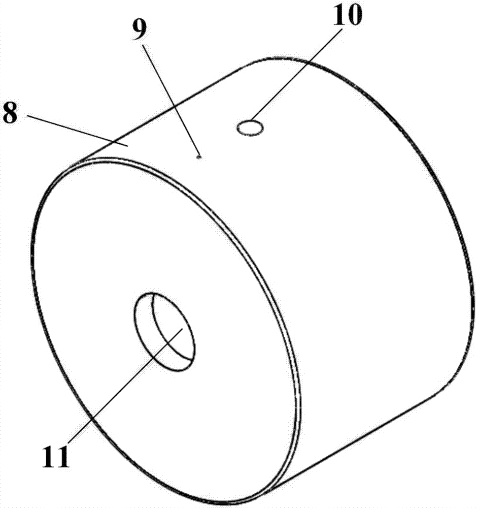
[0052] Such as image 3 and Figure 4 As shown, the propellant chamber 8 includes a main through hole 11 , two sub-chambers 12 , a propellant filling hole 10 , a monitoring hole 9 and a threaded hole 13 .

[0053] The above-mentioned main through holes are arranged along the central axis of the propellant chamber.

[0054] The two sub-cavities are parallel to each other and communicate with the main through hole.

[0055] The two sub-chambers are a propellant Y storage chamber 121 and a propellant X storage chamber 122, wherein t...


PUM


Abstract

The invention discloses a coaxial direct-current plasma nozzle based on dielectric barrier discharge. The coaxial direct-current plasma nozzle comprises an inner metal cylinder, metal bars, an outer insulating cylinder, a propellant chamber, an external electrode and a high-voltage power supply, wherein the propellant chamber comprises a main through hole and two branch chambers; the outer insulating cylinder comprises a nozzle outlet part, a mounting part, an outer nozzle hole groove, an inner cylinder fixing groove and a metal bar groove; an inner propellant X through hole is formed in the inner metal cylinder. The coaxial direct-current plasma nozzle is provided with a main spraying runner for a propellant X and a circular seam spraying runner for a propellant Y. The metal bars are distributed in the metal bar groove and are electrically connected with the high-voltage power supply. The nozzle outlet part is covered with the external electrode, and the external electrode is grounded. The coaxial direct-current plasma nozzle can improve the evaporating and mixing process of fuel and an oxidizing agent in the traditional coaxial direct-current nozzle and can shorten ignition delay, broaden flameout limit and improve combustion instability.

Description

technical field [0001] The invention relates to a power device for a rocket engine and an aeroengine, in particular to a coaxial direct current plasma nozzle based on a dielectric barrier discharge. Background technique [0002] Converting chemical energy into kinetic energy through combustion is the way most current power plants generate thrust. For conventional rocket engines, the fuel and oxidant are injected into the combustion chamber through the nozzle, and then atomized, evaporated, mixed and burned. A series of processes, the performance of the nozzle has an extremely important impact on this series of processes, therefore, the nozzle is one of the core components of the engine. [0003] Since the 1970s, researchers have carried out a large number of rocket engine nozzle design and test work. The main types of nozzles include shear type, swirl type, premixing type and impact type, among which the coaxial direct current Injectors represented by (shear) nozzles are ve...

Claims


Application Information

Patent Timeline
IPC IPC(8): F02K9/52
CPCF02K9/52
Inventor 聂万胜周思引车学科石天一何浩波苏凌宇王迪李金龙
Owner PLA PEOPLES LIBERATION ARMY OF CHINA STRATEGIC SUPPORT FORCE AEROSPACE ENG UNIV
Learn More