
Cleaning device for thermal equipment

A technology for cleaning devices and thermal equipment, applied in the directions of cleaning hollow objects, cleaning methods and utensils, cleaning methods using liquids, etc., can solve the problems of inconvenient cleaning of thermal equipment, and achieve convenient sewage discharge, increase service life, and place stability. Effect

Inactive Publication Date: 2017-11-07
颜秋羊
View PDF0 Cites 1 Cited by
  • Summary
  • Abstract
  • Description
  • Claims
  • Application Information

AI Technical Summary

Problems solved by technology

[0003] The purpose of the present invention is to provide a cleaning device for thermal equipment, which has the advantages of easy cleaning of thermal equipment and solves the problem of inconvenient cleaning of thermal equipment

Method used


Image

  • Cleaning device for thermal equipment
  • Cleaning device for thermal equipment
  • Cleaning device for thermal equipment

Examples


Embodiment Construction

[0016] The following will clearly and completely describe the technical solutions in the embodiments of the present invention with reference to the accompanying drawings in the embodiments of the present invention. Obviously, the described embodiments are only some, not all, embodiments of the present invention. Based on the embodiments of the present invention, all other embodiments obtained by persons of ordinary skill in the art without making creative efforts belong to the protection scope of the present invention.

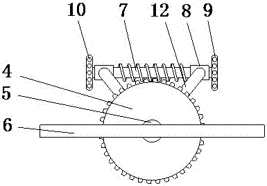
[0017] see Figure 1-3 , a thermal equipment cleaning device, comprising a housing 1, the back of the housing 1 is fixedly connected with support legs 15, the support legs 15 are distributed at the four corners of the back of the housing 1, by setting the support legs 15, the thermal equipment cleaning device can be placed more stable, the right side of the housing 1 is fixedly connected with a glass sheet 16, the glass sheet 16 is rectangular, by setting the ...


PUM


Abstract

The invention discloses a cleaning device for thermal equipment, which comprises a casing, the front of the casing is fixedly connected with a motor, and the rear end of the rotating shaft of the motor passes through the casing and extends to the inside of the casing to be movably connected with a rotating shaft. The rear end of the rotating shaft is movably connected with a bearing, the back of the bearing is fixedly connected with a tooth block, the bottom of the tooth block is fixedly connected with a connecting block, the inside of the housing is fixedly connected with a fixed rod, and the fixed rod The front of the tooth block is fixedly connected with the back of the connection block, and the surface of the tooth block is engaged with a threaded rod. The invention makes the thermal equipment easy to clean by arranging the motor, the rotating shaft, the bearing, the gear block, the connecting block, the fixed rod, the threaded rod, the bearing sleeve and the V-shaped block. Inhomogeneous mixing of substances can cause pipe burst accidents caused by local damage to thermal equipment, which is beneficial to people's use.

Description

technical field [0001] The invention relates to the technical field of thermal equipment, in particular to a thermal equipment cleaning device. Background technique [0002] In a heating plant or thermal power plant, the equipment that releases heat through fuel combustion and then uses the heat to heat water or heat water into steam, and then supplies heat to users or drives a generator to generate electricity through a steam turbine belongs to thermal equipment. In the system, there are boilers for fuel combustion, gas turbines, heaters in steam and water cycles, deaerators, condensers, feed water pumps, circulation pumps and other related auxiliary equipment, as well as thermal equipment such as industrial boilers and civil boilers. If the surface is covered with more than 80% scale, and the average scale thickness reaches or exceeds 1 mm, the thermal equipment should be chemically cleaned. Most common thermal equipment are directly injected with chemicals for cleaning. T...

Claims


Application Information

Patent Timeline
Patent Type & Authority Applications(China)
IPC IPC(8): B08B3/02B08B9/093B08B13/00
CPCB08B3/02B08B9/0936B08B13/00
Inventor 颜秋羊
Owner 颜秋羊
Learn More