
Antistatic flexible circuit board

A flexible circuit board, anti-static technology, applied in the direction of circuit devices, printed circuits, printed circuit components, etc., can solve the problems of narrow unit lines, poor ability to withstand electrostatic discharge, low yield rate of flexible circuit boards, etc., to achieve Easy to dissipate heat, avoid breakage, good anti-static effect

Inactive Publication Date: 2017-11-03
YANCHENG HUAXU OPTOELECTRONICS TECH CO LTD
View PDF0 Cites 6 Cited by
  • Summary
  • Abstract
  • Description
  • Claims
  • Application Information

AI Technical Summary

Problems solved by technology

[0002] Static electricity and electrostatic discharge are ubiquitous in our daily life, but for electronic devices, a slight electrostatic discharge that we cannot detect may cause serious damage to them. The rapid development of electronic technology has made the functions of electronic products It is becoming more and more powerful, but the volume is getting smaller and smaller, but this is at the expense of the increasing electrostatic sensitivity of electronic components. High integration means that the unit lines will become narrower and more resistant to electrostatic discharge. In addition, the materials used in a large number of new special devices are also electrostatic sensitive materials, so that electronic components, especially semiconductor material devices, require more and more electrostatic control in the environment during production, assembly and maintenance. However, in the production, use and maintenance of electronic products, a large number of polymer materials that are prone to static electricity are used in large quantities, which makes the yield rate of small flexible circuit boards lower.

Method used


Image

  • Antistatic flexible circuit board
  • Antistatic flexible circuit board

Examples


Embodiment Construction

[0014] The following will clearly and completely describe the technical solutions in the embodiments of the present invention with reference to the accompanying drawings in the embodiments of the present invention. Obviously, the described embodiments are only some, not all, embodiments of the present invention. Based on the embodiments of the present invention, all other embodiments obtained by persons of ordinary skill in the art without making creative efforts belong to the protection scope of the present invention.

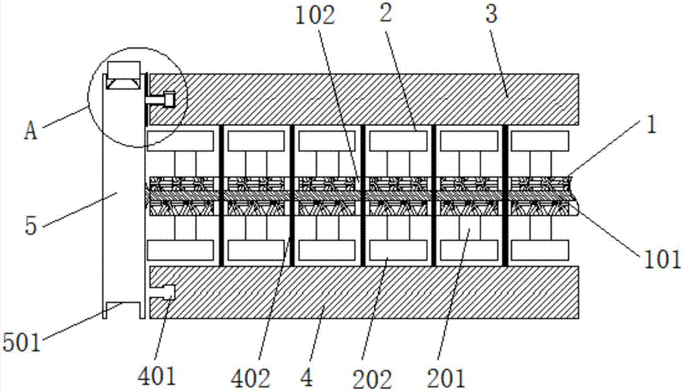
[0015] see Figure 1-2 , the present invention provides a technical solution: an antistatic flexible circuit board, including a substrate 1, support blocks 2 are distributed on the upper and lower surfaces of the substrate 1, and the surfaces of the support blocks 2 on both sides are respectively provided with a first copper foil plate 3 and The second copper foil plate 4, the support block 2 includes rubber pads 201 equidistantly distributed on the surface of...


PUM


Abstract

The invention discloses an anti-static flexible circuit board, which includes a base plate, and support blocks are distributed on the upper and lower surfaces of the base plate. The anti-static flexible circuit board has a simple structure, and provides a first copper foil board and a second copper foil board through the base plate. A certain rigid support ensures the overall stability of the circuit board, and is connected by equidistantly distributed adhesive boards to provide deformation space for the flexible bending of the first copper foil board and the second copper foil board to avoid excessive concentration of internal stress during bending At the same time, the deformation of the rubber pad weakens the curvature of the first copper foil board and the second copper foil board, and the cavity between the support blocks provides a heat dissipation channel for the heat generated by the operation of the circuit board, which is convenient for heat dissipation and ensures the normal operation of the circuit board. When working, the side cover provides end protection and connection support. The shrapnel and sliding strip ensure the grounding support of the circuit board, which is convenient for the diversion of static electricity. It can be hidden in the end groove without affecting the installation of the circuit board. The anti-static effect is good. Easy to produce and use.

Description

technical field [0001] The invention relates to the technical field of flexible circuit boards, in particular to an antistatic flexible circuit board. Background technique [0002] Static electricity and electrostatic discharge are ubiquitous in our daily life, but for electronic devices, a slight electrostatic discharge that we cannot detect may cause serious damage to them. The rapid development of electronic technology has made the functions of electronic products It is becoming more and more powerful, but the volume is getting smaller and smaller, but this is at the expense of the increasing electrostatic sensitivity of electronic components. High integration means that the unit lines will become narrower and more resistant to electrostatic discharge. In addition, the materials used in a large number of new special devices are also electrostatic sensitive materials, so that electronic components, especially semiconductor material devices, require more and more electrosta...

Claims


Application Information

Patent Timeline
IPC IPC(8): H05K1/02
CPCH05K1/0259H05K1/028
Inventor 李子考
Owner YANCHENG HUAXU OPTOELECTRONICS TECH CO LTD
Learn More