
Equipment state monitor

A technology of equipment status and monitoring instrument, applied in digital transmission systems, electrical components, transmission systems, etc., can solve the problems of difficulty in inspection of distributed equipment, fault location, and low fault diagnosis efficiency, and achieve convenient real-time processing and communication methods. Multiple choices and comprehensive detection parameters

Inactive Publication Date: 2017-11-03
四川忆思科技有限公司
View PDF5 Cites 2 Cited by
  • Summary
  • Abstract
  • Description
  • Claims
  • Application Information

AI Technical Summary

Problems solved by technology

[0003] The purpose of the present invention is to overcome the problems of difficult inspection, fault location, and low efficiency of fault diagnosis of existing distributed equipment in the field of traffic control, and provide an equipment status monitor with reasonable structure, reliable operation, and built-in large-capacity battery

Method used

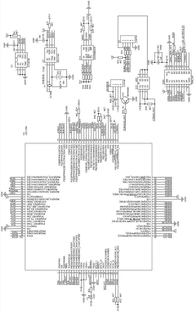
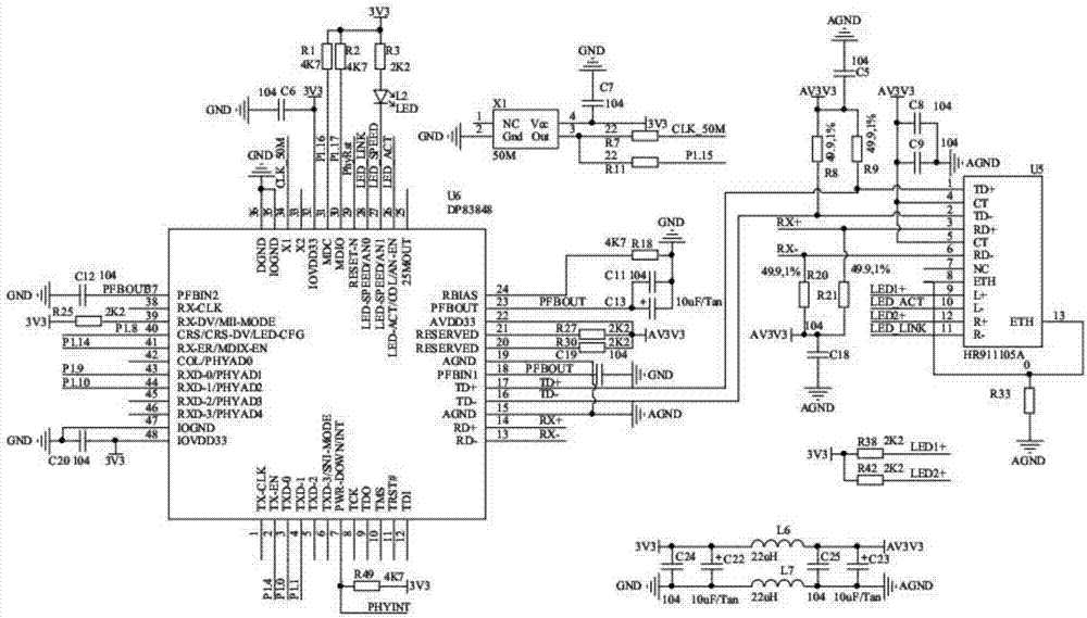

Image

  • Equipment state monitor
  • Equipment state monitor
  • Equipment state monitor

Examples


Embodiment Construction

[0020] In order to make the object, technical solution and advantages of the present invention clearer, the present invention will be further described in detail below in conjunction with the accompanying drawings and embodiments.

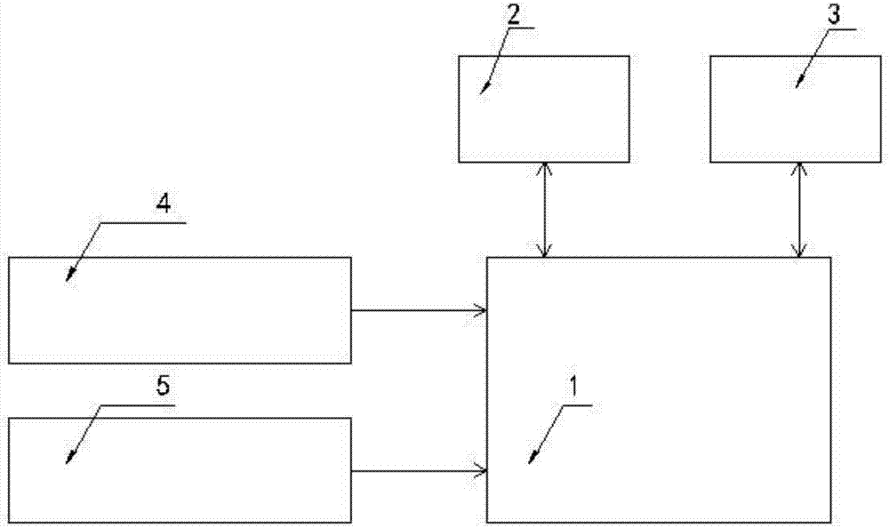
[0021] Such as figure 1 As shown, an equipment status monitor is characterized in that it includes an embedded control unit 1 , a wired network communication unit 2 , a wireless network communication unit 3 , a sensor unit 4 and a power supply unit 5 . The wired network communication unit 2 and the wireless network communication unit 3 are respectively connected to the embedded control unit 1 for one-way communication. The sensor unit 4 is connected to the embedded control unit 1 in two-way communication.

[0022] The sensor unit 4 collects the status information of the monitored equipment and transmits it to the embedded control unit 1 . The embedded control unit 1 calculates the received state information data, judges whether the monitored equi...


PUM


Abstract

The invention discloses an equipment state monitor which comprises an embedded control unit, a wired network communication unit, a wireless network communication unit, a sensor unit and a power supply unit. The wired network communication unit and the wireless network communication unit are in unidirectional communication connection with the embedded control unit. The sensor unit is in bidirectional communication connection with the embedded control unit. According to the equipment state monitor disclosed by the invention, various parameters of the sensor unit can be detected in real time and can be transmitted to a background server in real time by wired and wireless networks so as to implement centralized monitoring and abnormity warning; and the equipment state monitor is suitable for being popularized and applied.

Description

technical field [0001] The invention relates to the technical field of traffic control, in particular to an equipment status monitor. Background technique [0002] At present, with the development of technology, the production and operation of various industries rely on the close cooperation of various equipment. The monitoring of equipment operating environment and working status plays an important role in the long-term and stable operation of the equipment, as well as the timely positioning and maintenance of equipment failures. In the field of traffic control, for example, the maintenance of equipment such as electronic eyes and traffic signal controllers relies on personnel on-site inspections, or citizens provide fault information. There are great obstacles in the timeliness of fault reporting and fault location. Based on the above problems, the market There is a need for an equipment condition monitor that can monitor distributed equipment in the traffic control field...

Claims


Application Information

Patent Timeline
Patent Type & Authority Applications(China)
IPC IPC(8): H04L12/24H04L12/26
CPCH04L41/06H04L41/0631H04L41/0677H04L43/065H04L43/08
Inventor 傅成洪胡柯李华刚
Owner 四川忆思科技有限公司
Learn More