Frictional damping dynamic vibration absorber
A dynamic vibration absorber and friction damping technology, applied in the direction of shock absorbers, shock absorbers, springs/shock absorbers, etc., can solve the problems of small installation space for vibration reduction efficiency, achieve optimal friction damping energy consumption effect, and improve energy saving. Vibration efficiency, reducing the effect of mass ratio index requirements
- Summary
- Abstract
- Description
- Claims
- Application Information
AI Technical Summary
Problems solved by technology
Method used
Image
Examples
Embodiment 1
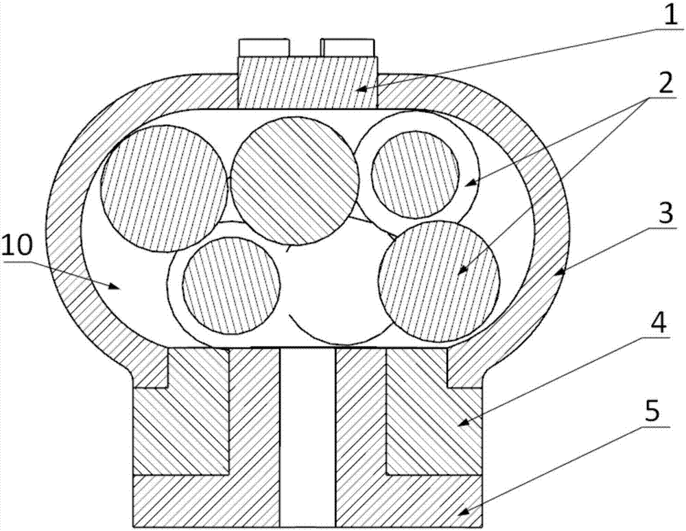
[0021] The elastic sleeve 4 is an elastic supporting structure, which is completely fixedly connected with the rigid inverted T-shaped base 5 and the spherical housing 3 . The damping ball 2 filled in the damping cavity 10) of the spherical housing 3 is a solid sphere. The top of the spherical housing 3 is equipped with an adjustment cap 1 for adjusting the size of the damping cavity 10). When the adjustment cap 1 is screwed in downwards, the movement range of the solid damping ball 2 in the vibration damping cavity 10) can be compressed. When the adjustment cap 1 When screwing upward, the movement range of the solid damping ball 2 in the damping cavity 10) can be expanded. When in use, first use modal test or modal simulation to determine the natural frequency and maximum mode shape position of the printed circuit board, according to the optimal tuning ratio formula in the dynamic vibration absorption theory The mass ratio of the vibration absorber of the present invention ...
Embodiment 2
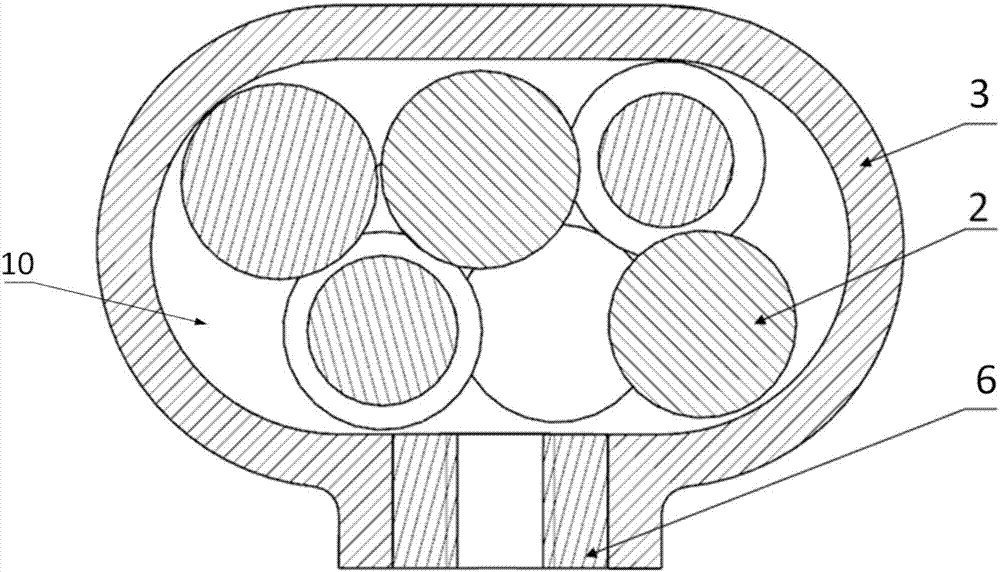
[0026] refer to image 3. The difference between this embodiment and the above-mentioned embodiment 1 is that the elastic sleeve 4 is removed, the spherical housing 3 is changed from a rigid structure to an elastic damping structure that removes the adjustment cap 1, and the inverted T-shaped base 5 is changed into an internal threaded pipe 6 , The spherical shell 3 is directly fixedly connected with the internally threaded pipe 6, and the other composition, installation and connection relations are the same as those in Embodiment 1.
Embodiment 3
[0028] refer to Figure 4 . The difference between this embodiment and the above-mentioned embodiment 1 is that the elastic sleeve 4 is replaced by a film spring 7 fixed on the open end of the spherical housing 3, the inverted T-shaped base 5 is changed into a T-shaped screw 9, and the T-shaped screw 9 The shaft shoulders are fixedly connected by nuts 8 through membrane springs 7, and the other composition structures are the same as in embodiment 1.
PUM
 Abstract
Description
Claims
Application Information
 - R&D
- Intellectual Property
- Life Sciences
- Materials
- Tech Scout
- Unparalleled Data Quality
- Higher Quality Content
- 60% Fewer Hallucinations
Browse by: Latest US Patents, China's latest patents, Technical Efficacy Thesaurus, Application Domain, Technology Topic, Popular Technical Reports.
© 2025 PatSnap. All rights reserved.Legal|Privacy policy|Modern Slavery Act Transparency Statement|Sitemap|About US| Contact US: help@patsnap.com


