
Piezoelectric ejection printing head and printing device provided with same

A piezoelectric jetting and printing head technology, applied in the field of printing devices and piezoelectric jetting printing heads, can solve the problems affecting the overall deformation of the laminated piezoelectric ceramics, reducing the printing head jetting accuracy, contusion and collapse of the edges and corners of the ceramics, etc. Low cost of use, accurate jet printing action, and the effect of avoiding extrusion damage

Active Publication Date: 2017-10-31
北京派和智能装备技术有限公司
View PDF13 Cites 0 Cited by
  • Summary
  • Abstract
  • Description
  • Claims
  • Application Information

AI Technical Summary

Problems solved by technology

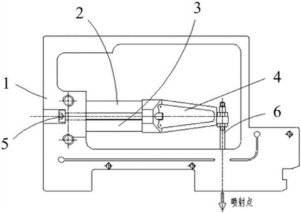
[0005] 1) Since the interior of the piezoelectric ceramic is a whole piece, the deformation of any part during the working process will be limited by the boundary conditions of the adjacent part, which directly limits and affects the overall deformation of the laminated piezoelectric ceramic, resulting in the print head The injection accuracy is reduced;
[0006] 2) The end face of the piezoelectric ceramic is approximately flat. During the working process, the corners of the end face of the piezoelectric ceramic will be sheared and squeezed, which will easily bruise and collapse the corners of the ceramic;
[0007] 3) Since the piezoelectric ceramic is a whole piece, if any layer of piezoelectric ceramic inside the piezoelectric ceramic is damaged, it is necessary to replace the piezoelectric ceramic as a whole, and the use cost is high

Method used


Image

  • Piezoelectric ejection printing head and printing device provided with same
  • Piezoelectric ejection printing head and printing device provided with same
  • Piezoelectric ejection printing head and printing device provided with same

Examples


Embodiment Construction

[0027] In order to make the technical problems, technical solutions and advantages to be solved by the present invention clearer, the following will describe in detail with reference to the drawings and specific embodiments.

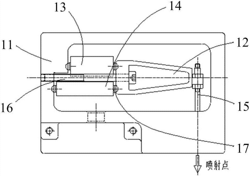
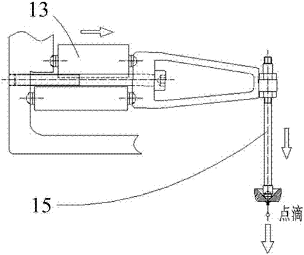
[0028] In one aspect, the present invention provides a piezoelectric jet printing head, such as figure 2 As shown, it includes a valve body 11, a displacement amplification mechanism 12, an upper piezoelectric ceramic 13, a lower piezoelectric ceramic 14 and a striker 15, wherein:

[0029] The displacement amplifying mechanism 12 is arranged inside the valve body 11 through the fixed rod 16, and the upper and lower piezoelectric ceramics 14 are respectively arranged above and below the fixed rod 16, and one side of the upper and lower piezoelectric ceramics 14 is connected to the valve body through a ceramic protrusion 17. On the inner wall of the valve body 11, the other side of the upper and lower piezoelectric ceramics 14 is connected to both sides o...


PUM


Abstract

The invention discloses a piezoelectric ejection printing head and a printing device provided with the same and belongs to the field of piezoelectric ejection. The piezoelectric ejection printing head comprises a valve body, a displacement amplifying mechanism, an upper piezoelectric ceramic, a lower piezoelectric ceramic and an impact bar, wherein the displacement amplifying mechanism is arranged in the valve body through a fixed rod; the upper piezoelectric ceramic and the lower piezoelectric ceramic are separately arranged on and under the fixed rod; one sides of the upper piezoelectric ceramic and the lower piezoelectric ceramic are connected to the inner wall of the valve body through ceramic bulges while the other sides of the upper piezoelectric ceramic and the lower piezoelectric ceramic are connected to two sides of the back end of the displacement amplifying mechanism through ceramic bulges; and the front end of the displacement amplifying mechanism is connected to the impact bar. Compared with the prior art, the piezoelectric ejection printing head disclosed by the invention has the advantages of being high in ejection precision, capable of preventing ceramic edges and corners from being extruded and damaged and low in cost.

Description

technical field [0001] The invention relates to the field of piezoelectric jetting, in particular to a piezoelectric jetting printing head and a printing device with the printing head. Background technique [0002] Fluid jet printing technology is a key technology in the fields of microelectronic packaging, electroacoustic device packaging, and LED packaging. It can be structured to form points, lines, surfaces (coating) and various graphics, and is widely used in additive manufacturing, electronic Manufacturing, package flipping, and chip coating. Fluid jet printing technology precisely distributes fluid in a controlled manner, which can transfer ideal size fluid (flux, conductive glue, epoxy resin and adhesive, etc.) In order to realize the mechanical or electrical connection between components, this technology requires the jet printing system to have good operability, high jet printing speed, good consistency and high precision of dots. [0003] Fluid jet printing techn...

Claims


Application Information

Patent Timeline
IPC IPC(8): B41J2/045B41J2/14
CPCB41J2/045B41J2/14
Inventor 张振甲张淑兰
Owner 北京派和智能装备技术有限公司
Learn More