
Single inductor bridgeless APFC circuit based on IGBT module

A single inductance and circuit technology, applied in high-efficiency power electronic conversion, electrical components, output power conversion devices, etc., can solve the problems of large space occupation, high cost, and unsatisfactory

Pending Publication Date: 2017-10-24
SHANGHAI MUNICIPAL ELECTRIC POWER CO
View PDF4 Cites 3 Cited by
  • Summary
  • Abstract
  • Description
  • Claims
  • Application Information

AI Technical Summary

Problems solved by technology

[0004] After searching the existing technology of bridgeless power factor correctors, for example, the document "Analysis and Design of Single-phase Bridgeless Power Factor Corrector" published in the 8th issue of "Electrical Applications" in 2015 proposes a single-phase non-circulating current type Bridgeless APFC adopts single-cycle control, but this circuit is the same as the traditional bridgeless APFC, it is a dual-inductance circuit, the cost is high, and the space occupied is large, which does not meet the development direction of the current power factor corrector.
[0005] Based on the above, after searching the existing technologies of bridgeless power factor correctors, it is found that the existing circuits are all double-inductor structures, which cannot meet the needs of current practical applications.

Method used


Image

  • Single inductor bridgeless APFC circuit based on IGBT module
  • Single inductor bridgeless APFC circuit based on IGBT module
  • Single inductor bridgeless APFC circuit based on IGBT module

Examples


Embodiment 1

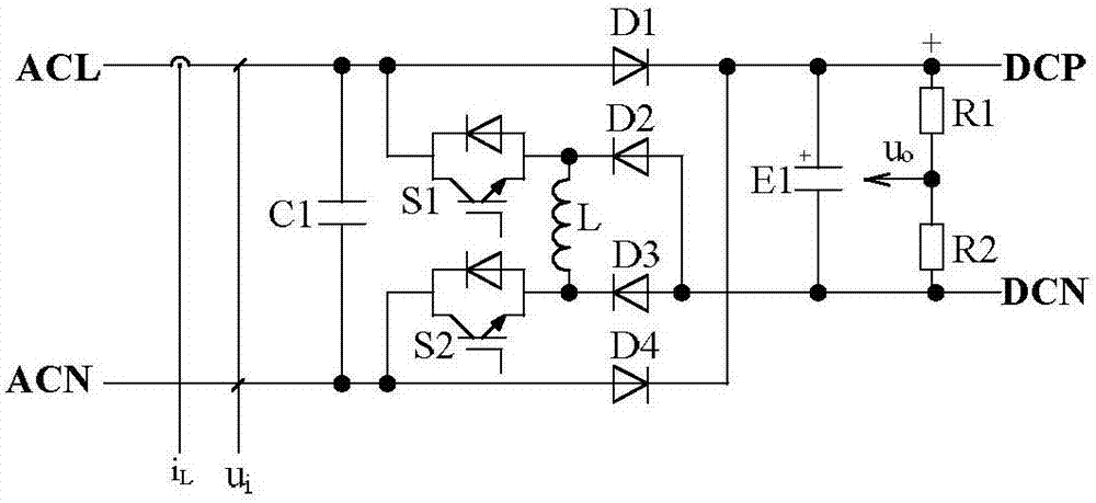
[0047] A single-inductance bridgeless APFC circuit based on an IGBT module of the present invention includes an AC filter capacitor C1, a first IGBT module S1, a second IGBT module S2, an inductor L, a first power diode D1, a second power diode D2, a second The third power diode D3, the fourth power diode D4, the DC filter capacitor E1, the first voltage dividing resistor R1, and the second voltage dividing resistor R2.

[0048] The anode of the first power diode D1, the first end of the AC filter capacitor C1, and the collector of the first IGBT module S1 are connected to the live wire of the power supply to form an input voltage and input current sampling terminal, and the input current i can be sampled at this point L and input voltage u i .

[0049] The anode of the fourth power diode D4, the second end of the AC filter capacitor C1 and the collector of the second IGBT module S2 are connected to the neutral line of the power supply.

[0050] The emitter of the first IGBT...

Embodiment 2

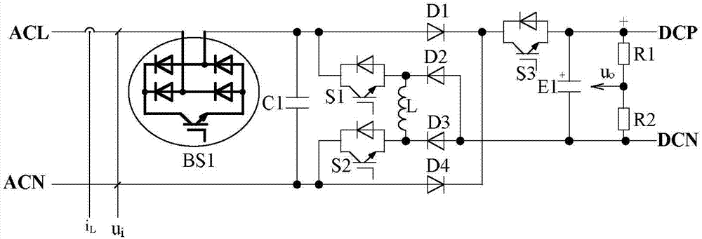
[0073] A single-inductance bridgeless APFC circuit based on IGBT modules of the present invention includes an AC filter capacitor C1, a first IGBT module S1, a second IGBT module S2, a third IGBT module S3, an inductor L, a first power diode D1, and a second IGBT module. The second power diode D2, the third power diode D3, the fourth power diode D4, the DC filter capacitor E1, the first voltage dividing resistor R1, the second voltage dividing resistor R2, and the bidirectional switch BS1.

[0074] The first end of the bidirectional switch BS1 is connected to the live wire of the power supply to form an input voltage and input current sampling end, at which point the input current i can be sampled L and input voltage u i .

[0075] The second end of the bidirectional switch BS1 is connected to the first end of the AC filter capacitor C1 , the collector of the first IGBT module S1 and the anode of the first power diode D1 .

[0076] The anode of the fourth power diode D4, the...


PUM


Abstract

The invention discloses a single inductor bridgeless APFC circuit based on an IGBT module, and the circuit comprises an AC filter capacitor C1, a first IGBT module S1, a second IGBT module S2, an inductor L, a first power diode D1, a second power diode D2, a third power diode D3, a fourth power diode D4, a DC filter capacitor E1, a first divider resistor R1 and a second divider resistor R2; the anode of the first power diode D1, the first end portion of the AC filter capacitor C1 and a collector electrode of the first IGBT module S1 are connected with a power supply fire wire; the anode of the fourth power diode D4, the second end portion of the AC filter capacitor C1 and the collector of the second IGBT module S2 are connected with a power supply zero line; the emitting electrode of the first IGBT module S1, the first end portion of the inductor L and the cathode of the second power diode D2 are connected; and the emitting electrode of the second IGBT module S2, the second end portion of the inductor L and the cathode of the third power diode D3 are connected.

Description

technical field [0001] The invention relates to a single-inductance bridgeless APFC circuit based on an IGBT module in the field of single-phase power factor correction. Background technique [0002] In a single-phase power grid, an uncontrolled rectifier bridge and electrolytic capacitors are used as the power electronic converter of the front-stage circuit. No matter what kind of impedance load is connected to the rear stage, it is a nonlinear load, which will cause harmonic current pollution to the power grid and cannot meet the requirements. The harmonic current limit specified in IEC 61000-3-2 and IEC 61000-3-1, and the grid side power factor is low, so power factor correction measures must be adopted. [0003] However, the traditional bridgeless power factor corrector must use two inductors, the current flow direction is uncertain, the low-frequency diode and the diode in the IGBT module may be turned on at the same time, which increases the instability factor, and the...

Claims


Application Information

Patent Timeline
IPC IPC(8): H02M1/42
CPCH02M1/4208Y02B70/10
Inventor 杨振睿杨喜军卢广震徐剑金琪朱真汪传毅王斌周鑫何正宇蔡斌石英超顾晓鸣叶志刚金皓纯钟鸣赵瑞刘烨曹芸杨波李文雯戴岭金伟陈震解蕾徐刚
Owner SHANGHAI MUNICIPAL ELECTRIC POWER CO
Learn More