Wheel hub motor and position signal processing method thereof
A hub motor and motor shaft technology, applied in the field of electric vehicles, to achieve the effect of increasing resolution, improving accuracy, and improving control performance
- Summary
- Abstract
- Description
- Claims
- Application Information
AI Technical Summary
Problems solved by technology
Method used
Image
Examples
Embodiment 1
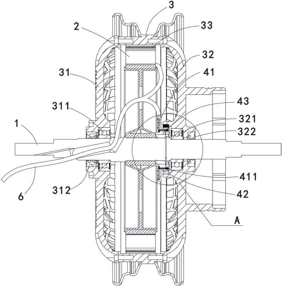
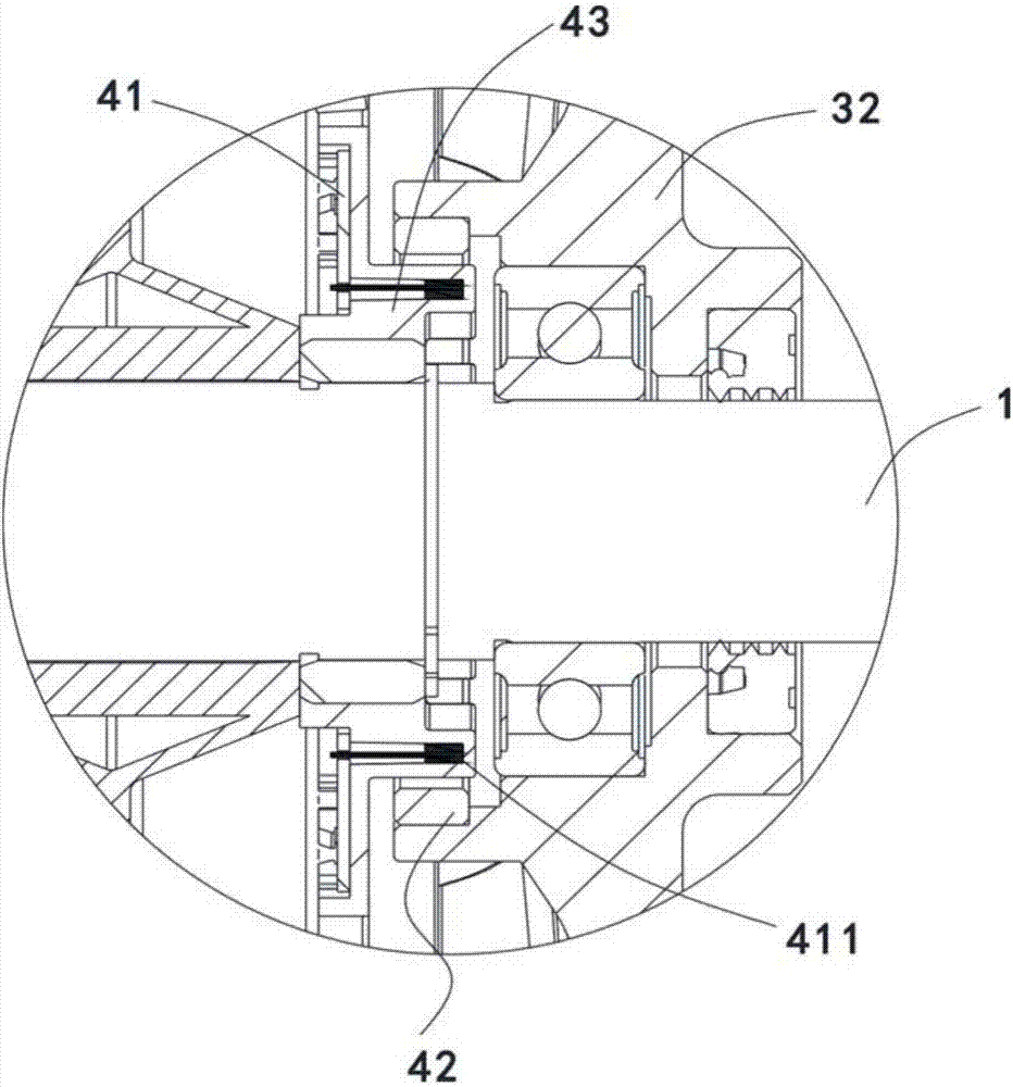
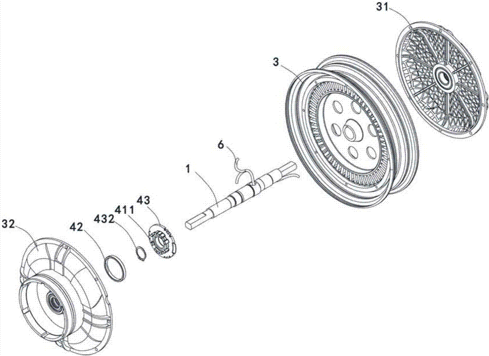
[0052] like Figure 1-4 As shown, a wheel hub motor includes a motor shaft 1, a stator 2 fixed on the motor shaft 1 and wound with a three-phase motor power line, and a rotor 3 that is sleeved on the outside of the stator 2 and pasted with N-pole magnetic steel 33. The rotor 3 has two The left end cover 31 and the right end cover 32 for installing the brake device are installed on the side by screws, the left end cover 31 is rotatably fixed on the motor shaft 1 through the left bearing 311, and the left end cover 31 located outside the left bearing 311 and the motor shaft 1 Also be provided with oil seal 312 between, play waterproof effect, right end cover 32 is rotatably fixed on the motor shaft 1 by right bearing 321, is also provided with oil seal 322 between the right end cover 32 outside right bearing 321 and motor shaft 1.
[0053] The inner side of the hub motor is located on the opposite side of the outlet hole on the stator 2, and a position detection device is instal...
Embodiment 2
[0065] like Figure 8-12 As shown, the hub motor in this embodiment differs from that in Embodiment 1 in that the position detection device is arranged outside the left end cover 31 and on the same side as the outlet hole, and the signal output cable 7 of the position detection device is connected to the motor power line Cables 6 are output independently of each other.
[0066]The position detection device includes a housing 5 installed on the motor shaft 1, a bushing 52 for installing the magnetic ring 42 and a fixing frame 51 for installing the PCB board 41 are installed in the housing 5, and the bushing 52 is positioned by passing through the notch. It is connected to the right end cover 32 by screws, and the bushing 52 and the housing 5 are sealed and connected by a sealing ring 53 . The magnetic ring 42 is glued on the bushing 52, and is integrally installed on the outside of the right end cover 32, and rotates with the right end cover 32 and the rotor. The fixing frame...
PUM
 Abstract
Description
Claims
Application Information
 - R&D
- Intellectual Property
- Life Sciences
- Materials
- Tech Scout
- Unparalleled Data Quality
- Higher Quality Content
- 60% Fewer Hallucinations
Browse by: Latest US Patents, China's latest patents, Technical Efficacy Thesaurus, Application Domain, Technology Topic, Popular Technical Reports.
© 2025 PatSnap. All rights reserved.Legal|Privacy policy|Modern Slavery Act Transparency Statement|Sitemap|About US| Contact US: help@patsnap.com


