
Washing machine and clutch mechanism thereof

A clutch mechanism and washing machine technology, applied in the field of washing machines, can solve the problems of waste of space and materials, waste of axial space of the clutch mechanism, difficulty in meshing, etc., and achieve the effects of reducing production costs, simplifying structure and assembly process

Active Publication Date: 2017-10-24
GUANGDONG WELLING ELECTRIC MACHINE MFG +1
View PDF5 Cites 2 Cited by
  • Summary
  • Abstract
  • Description
  • Claims
  • Application Information

AI Technical Summary

Problems solved by technology

The driving device of the dial ring in the prior art is generally more complex, with many parts, and some need to set a separate driving motor to complete the clutch action, which has a negative impact on cost control, simplification of the assembly process and ensuring the stability of use; the axial dimension design It is not compact enough to waste the axial space of the clutch mechanism, and the washing capacity is reduced when the volume of the washing machine remains unchanged; the design of the clutch teeth is unreasonable, it is difficult to enter the mesh, and the meshing noise is large; the design of some parts is redundant, resulting in space and material constraints. double waste

Method used


Image

  • Washing machine and clutch mechanism thereof
  • Washing machine and clutch mechanism thereof
  • Washing machine and clutch mechanism thereof

Examples


Embodiment Construction

[0037]Embodiments of the present invention are described in detail below, examples of which are shown in the drawings, wherein the same or similar reference numerals designate the same or similar elements or elements having the same or similar functions throughout. Apparently, the embodiments described below by referring to the figures are exemplary, and are only for explaining the present invention, and should not be construed as limiting the present invention.

[0038] In the description of the embodiments of the present invention, it should be understood that the terms "upper", "lower", "left", "right", "top", "bottom", "inner", "outer" and the like indicate directions Or the positional relationship is based on the orientation or positional relationship shown in the drawings, which is only for the convenience of describing the embodiment of the present invention and simplifying the description, and does not indicate or imply that the referred device or element must have a sp...


PUM


Abstract

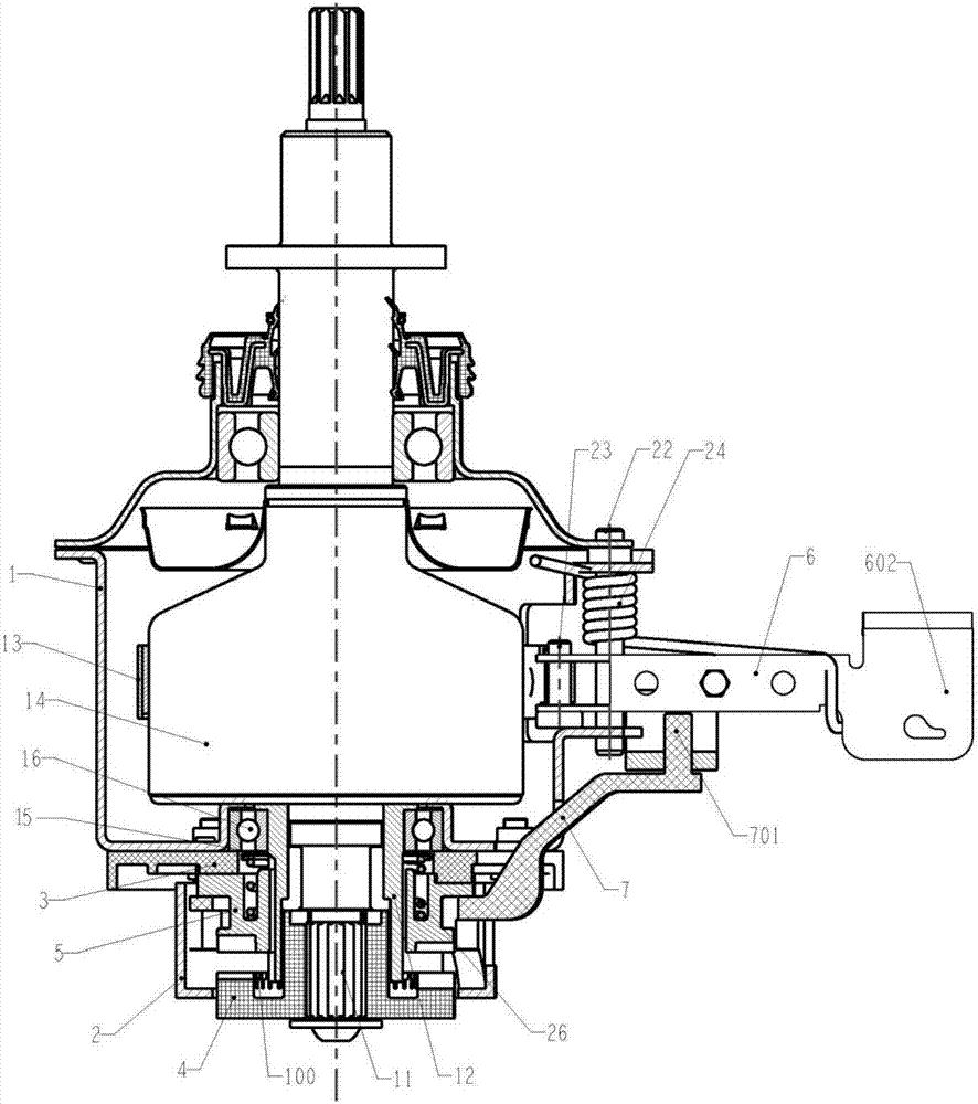
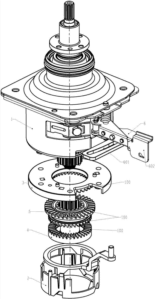
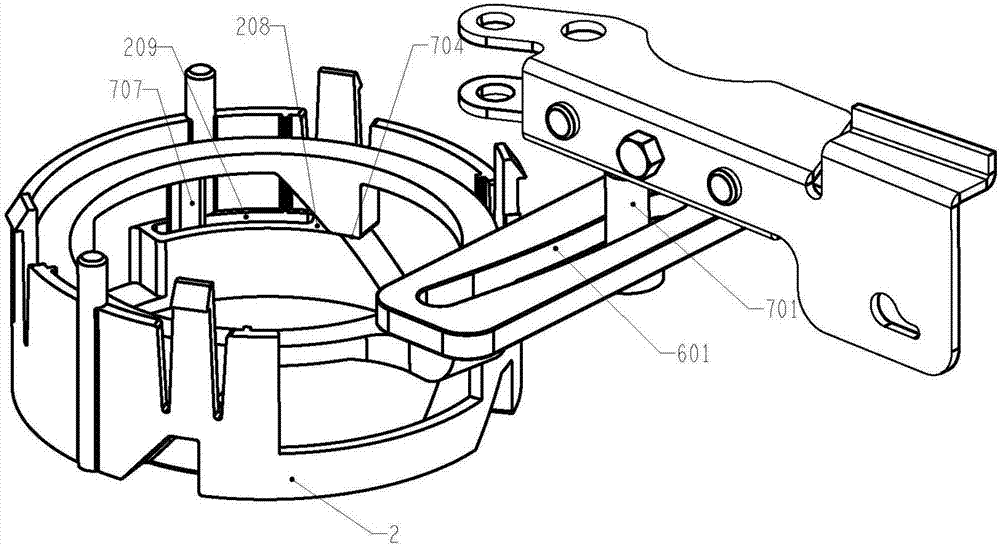
The invention relates to the field of washing machines and discloses a washing machine and a clutch mechanism thereof. The clutch mechanism comprises an input shaft (11), an input shaft sleeve (12), a clutch shaft sleeve (5), a shifting ring (7), a shifting ring support (2) and a shifting rod (6). The input shaft sleeve (12) externally sleeves the input shaft (11); the clutch shaft sleeve (5) externally sleeves the input shaft sleeve (12) and is capable of axially moving to realize switching between working conditions of dewatering / washing; the shifting ring (7) is used for supporting and driving the clutch shaft sleeve (5) to move axially; the shifting ring support (2) is used for mounting of the shifting ring (7) and connected with the shifting ring (7) to form a screw pair. The shifting rod (6) rotates in a horizontal plane perpendicular to the axis of the input shaft (11) to drive the shifting ring (7) to move helically in the shifting ring support (2) so as to drive the clutch shaft sleeve (5) to move axially. By adoption of the technical scheme, the clutch mechanism is structurally simplified, and manufacturing cost of the washing machine is reduced.

Description

technical field [0001] The invention relates to the field of washing machines, in particular to a clutch mechanism of the washing machine, and further, the invention also relates to a washing machine with the clutch mechanism. Background technique [0002] An important component of the washing machine, the transmission system of the washing machine (that is, the deceleration clutch mechanism) is used to realize the conversion of the elution conditions of the washing machine. It has four functions: transmission, deceleration, clutch, and brake. The gear meshing clutch mode is one of the main clutch modes of the deceleration clutch mechanism of the existing washing machine. [0003] The spiral clutch method is a common form of the existing tooth meshing clutch. The structure to realize the spiral clutch method is generally composed of a ring bracket fixed on the installation part, a ring, a clutch sleeve and a ring driving device. The ring bracket is set coaxially with the in...

Claims


Application Information

Patent Timeline
Patent Type & Authority Applications(China)
IPC IPC(8): D06F37/30D06F37/40
CPCD06F37/30D06F37/40Y02B40/00
Inventor 闫甜甜胡义明吴迪陈金涛
Owner GUANGDONG WELLING ELECTRIC MACHINE MFG
Learn More