Exhaust heat recovery device
A technology of exhaust heat recovery and heat recovery device, which is applied in the direction of exhaust device, muffler device, heat exchanger, etc., can solve the problems of cooling water temperature rise, cooling water boiling, abnormal sound of heat recovery device, etc., and achieves boiling suppression. Effect
- Summary
- Abstract
- Description
- Claims
- Application Information
AI Technical Summary
Problems solved by technology
Method used
Image
Examples
no. 1 approach
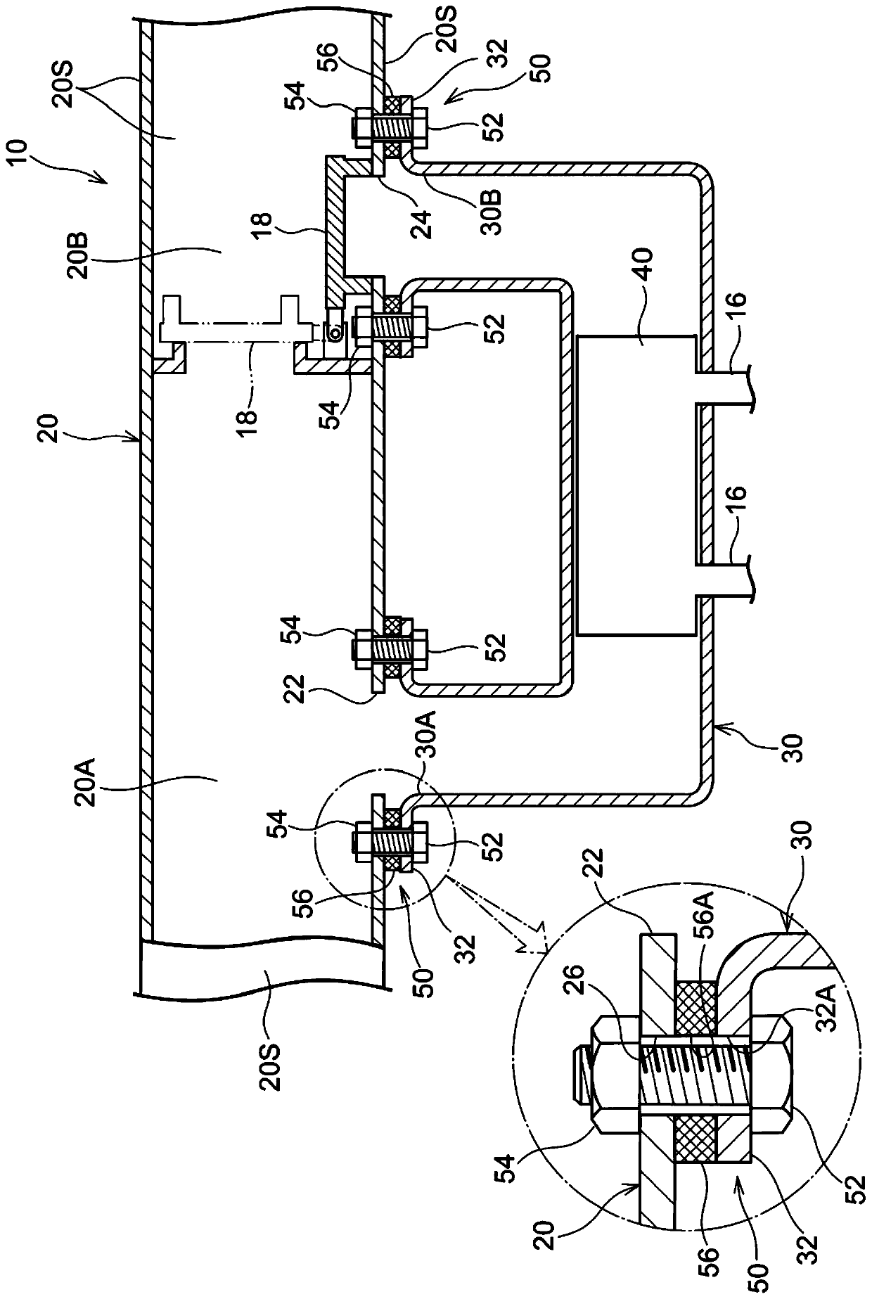
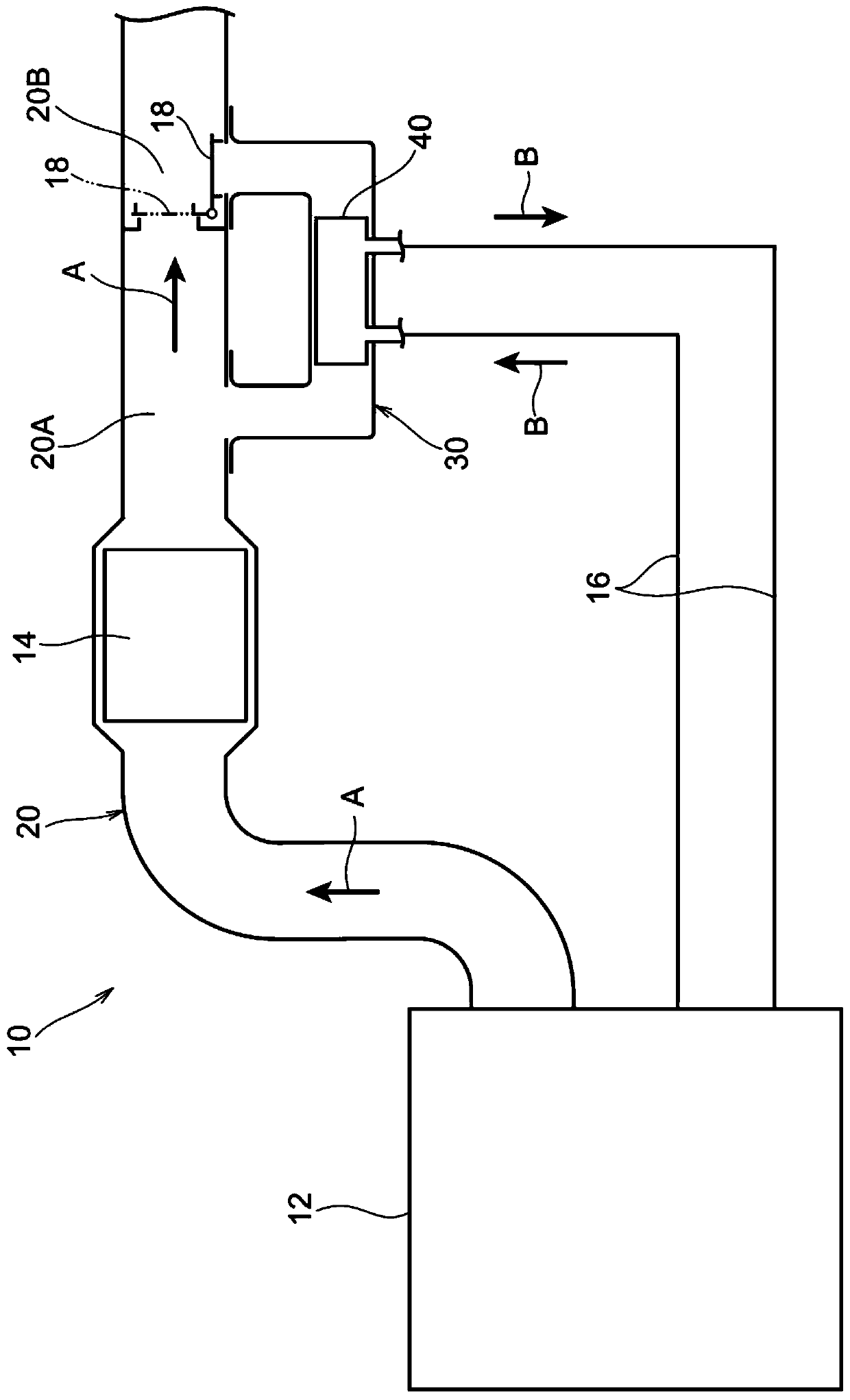
[0035] Below, use figure 1 and figure 2 The exhaust heat recovery device 10 according to the first embodiment will be described, and next, the heat transfer suppression mechanism 50 applied to the exhaust heat recovery device 10 will be described. In addition, hereinafter, the upstream side and the downstream side of the flow direction of the exhaust gas may be simply referred to as "upstream side" and "downstream side", respectively.
[0036] About Exhaust Heat Recovery Unit 10
[0037] like figure 2 As shown, the exhaust heat recovery device 10 recovers the heat of the exhaust gas of the engine 12 of the automobile by exchanging heat with the cooling water in the heat recovery device 40 described later, and uses it to promote the warming up of the engine 12. -up) and other devices.
[0038] like figure 1 As shown, the exhaust heat recovery device 10 has a tubular first pipe 20 . In the present embodiment, the first pipe 20 is formed into a tubular shape by joining me...
no. 2 approach
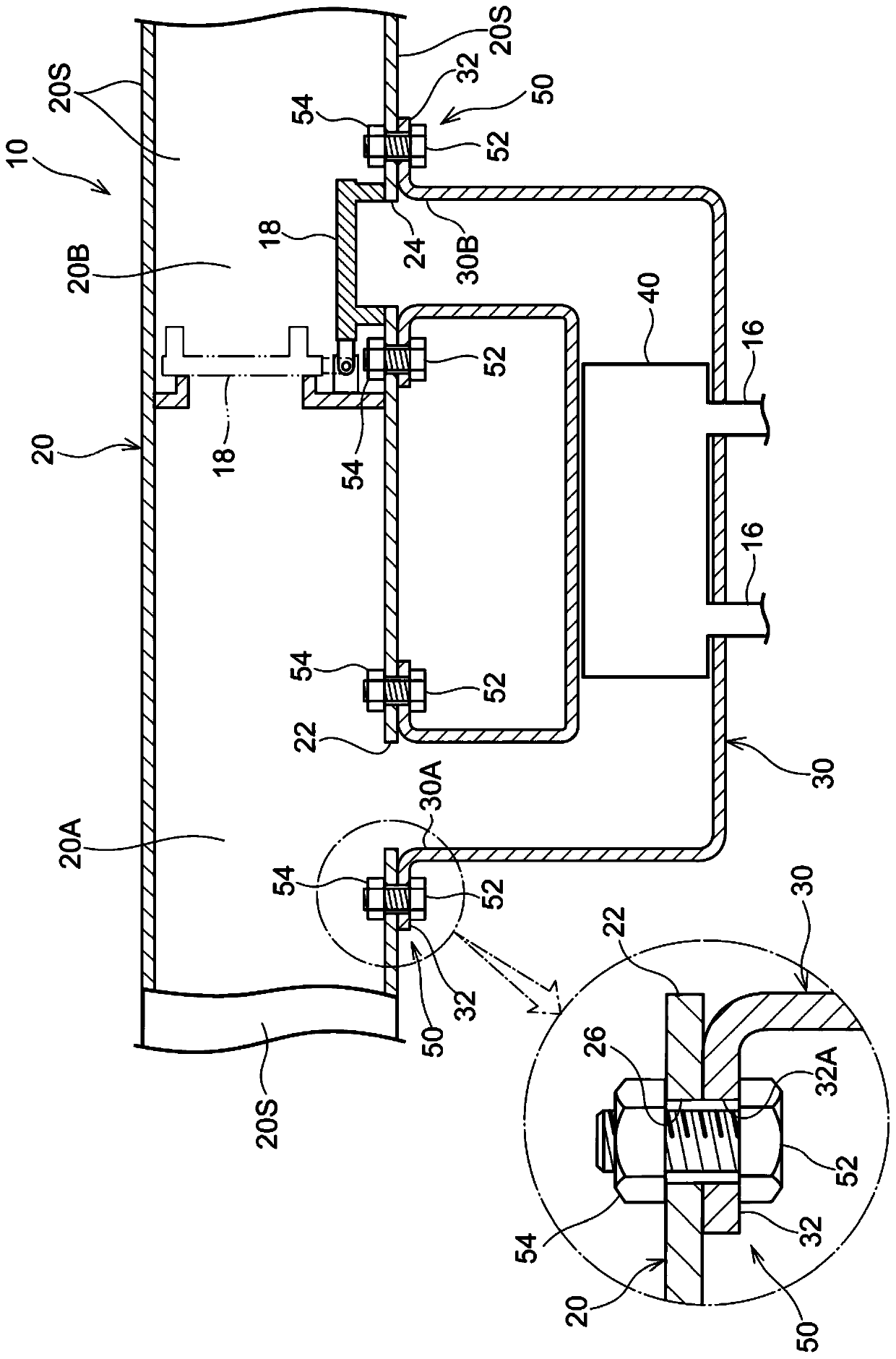
[0061] Below, use Figure 4 The exhaust heat recovery device 60 of the second embodiment will be described. The exhaust heat recovery device 60 of the second embodiment has the same configuration as the exhaust heat recovery device 10 of the first embodiment except for the heat transfer suppression mechanism 50 . Hereinafter, the heat transfer suppressing mechanism 50 of the exhaust heat recovery device 60 will be described. In addition, in Figure 4 In , the same reference numerals are attached to components configured in the same manner as those of the exhaust heat recovery device 10 of the first embodiment.
[0062] In the heat transfer suppression mechanism 50 of the exhaust heat recovery device 60, the heat insulating material 56, the bolt 52, and the weld nut 54 are omitted, and the second piping flange 32 of the second piping 30 is directly joined to the first piping 20 by laser welding. . In addition, in Figure 4 In the figure, for convenience of description, the...
no. 3 approach
[0066] Below, use Figure 5 The exhaust heat recovery device 70 of the third embodiment will be described. The exhaust heat recovery device 70 of the third embodiment has the same configuration as the exhaust heat recovery device 10 of the first embodiment except for the heat transfer suppression mechanism 50 . Hereinafter, the heat transfer suppression mechanism 50 of the exhaust heat recovery device 70 will be described. In addition, in Figure 5 In , the same reference numerals are attached to components configured in the same manner as those of the exhaust heat recovery device 10 of the first embodiment.
[0067] The heat insulating material 56 is omitted in the heat transfer suppressing mechanism 50 of the exhaust heat recovery device 70 . Furthermore, the heat transfer suppressing mechanism 50 of the exhaust heat recovery device 70 has a first piping flange 28 as a "first flange" formed on the first piping 20, and the first piping flanges 28 are respectively formed on...
PUM
 Abstract
Description
Claims
Application Information
 - R&D
- Intellectual Property
- Life Sciences
- Materials
- Tech Scout
- Unparalleled Data Quality
- Higher Quality Content
- 60% Fewer Hallucinations
Browse by: Latest US Patents, China's latest patents, Technical Efficacy Thesaurus, Application Domain, Technology Topic, Popular Technical Reports.
© 2025 PatSnap. All rights reserved.Legal|Privacy policy|Modern Slavery Act Transparency Statement|Sitemap|About US| Contact US: help@patsnap.com


