Nozzle moving device and automatic positioning method
A mobile device and print head technology, applied in power transmission devices, printing, transfer materials, etc., can solve the problem that the print head cannot automatically scan the edge and position the code, so as to facilitate cleaning and maintenance work, reduce power load, and save equipment investment. Effect
- Summary
- Abstract
- Description
- Claims
- Application Information
AI Technical Summary
Problems solved by technology
Method used
Image

Examples
Embodiment 1
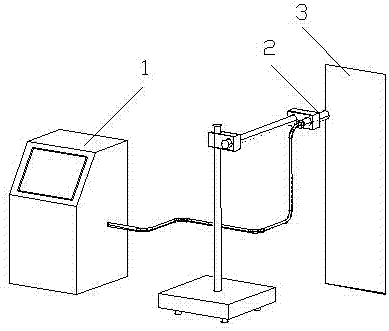
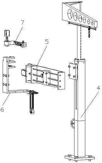
[0028] Example 1 : see figure 1 , a nozzle moving device, the nozzle moving device includes a base 4, a traverse mechanism 5, a patrol frame 6 and a nozzle bracket 7, the traverse mechanism 5 is arranged on the base 4, and the nozzle bracket 7 is installed on the patrol On the side bracket 6, and together with the side patrol bracket 7, realize the side patrol and nozzle positioning functions through the traverse mechanism. The height of the nozzle can be adjusted by rotating the screw rod with the hand wheel on the base. There is a rotating motor on the side patrol bracket, and when the nozzle needs to be cleaned and maintained, the nozzle bracket and the nozzle can be quickly moved from the working position to the maintenance station.
Embodiment 2
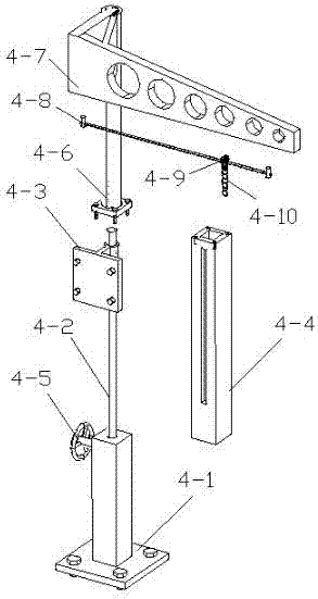
[0029] Example 2 : see figure 1 , as an improvement of the present invention, the base 4 includes a base 4-1, a height adjustment screw 4-2, a positioning block 4-3, a lifting chamber 4-4, a hand wheel 4-5, and a column 4-6 , cantilever 4-7, slide rail 4-8, pulley 4-9 and suspension chain 4-10, wherein the upper end of the base 4-1 is provided with a rectangular upgrade cavity 4-4, and the inside of the upgrade cavity 4-4 is set There is a height-adjusting screw rod 4-2, and the handwheel 4-5 that adjusts the rotation of the height-adjusting screw rod 4-2 is installed on the side of the base 4-1, and the positioning block 4-3 is set on the height-adjusting screw rod 4-2 through threads. Up, by rotating the hand wheel 4-5 to adjust the positioning block 4-3 to move vertically up and down along the guide groove on the side of the upgrading cavity 4-4, a column 4-6 is arranged on the upper end of the upgrading cavity 4-4, and the column 4 The upper end of -6 is set with a ca...
Embodiment 3
[0030] Example 3 : see figure 1 , as an improvement of the present invention, the traversing mechanism includes a bottom plate 5-1, a guide rod 5-2, a traversing screw 5-3, a slide table 5-4, a traversing servo motor 5-5 and a proximity switch 5-6, the transverse movement mechanism 5 is installed on the positioning block 4-3 with bolts through its aluminum alloy base plate 5-1, and the base plate 5-1 is provided with two stainless steel material guide rods 5-2 and a transverse movement The screw mandrel 5-3, the slide table 5-4 made of aluminum alloy is set on the guide rod 5-2 and a traversing screw mandrel 5-3 through the screw hole and the guide hole, and one end of the bottom plate 5-1 is equipped with a traversing The servo motor 5-5, the traverse servo motor 5-5 is connected with the traverse screw rod 5-3 through a coupling, and the forward and reverse rotation of the traverse servo motor 5-5 drives the traverse screw rod 5-3 to rotate and control The slide table 5...
PUM
 Abstract
Description
Claims
Application Information
 - R&D
- Intellectual Property
- Life Sciences
- Materials
- Tech Scout
- Unparalleled Data Quality
- Higher Quality Content
- 60% Fewer Hallucinations
Browse by: Latest US Patents, China's latest patents, Technical Efficacy Thesaurus, Application Domain, Technology Topic, Popular Technical Reports.
© 2025 PatSnap. All rights reserved.Legal|Privacy policy|Modern Slavery Act Transparency Statement|Sitemap|About US| Contact US: help@patsnap.com